Method for designing a flight vehicle

a flight vehicle and design method technology, applied in the field of flight vehicle design methods, can solve the problems of long process, inability to design iterations, and limitations of conventional flight vehicle design methodologies in aerodynamic scope, so as to reduce the cost, reduce the time involved, and predict the effect of air load

Inactive Publication Date: 2011-03-22
TEXTRON INNOVATIONS
View PDF4 Cites 17 Cited by
  • Summary
  • Abstract
  • Description
  • Claims
  • Application Information

AI Technical Summary

Benefits of technology

[0006]Therefore, it is an object of the present invention to provide an improved method for designing a flight vehicle.
[0011]The present invention provides significant advantages, including: (1) more reliably predicting air loads on a flight vehicle structure; (2) providing the air load predictions at a lower cost and in a shorter amount of time; and (3) minimizes operator variability.

Problems solved by technology

Conventional flight vehicle design methodologies have limitations in aerodynamic scope, the time to determine limit loads in the flight vehicle, and varying techniques in flight maneuver simulations.
The criteria are not sufficiently specific to result in unique flight conditions in satisfying the required flight parameter combinations.
Thus, in addition to requiring many iterations in order to converge on the required parameters, the conventional simulation process is user dependent and not repeatable.
The time involved does not allow design iterations to optimize the limit load condition.
The process of applying fuselage air load distributions to the structural finite element model is a lengthy process, involving intensive manual manipulations for each aerodynamic loading condition.

Method used


Image

  • Method for designing a flight vehicle
  • Method for designing a flight vehicle
  • Method for designing a flight vehicle

Examples


Embodiment Construction

[0017]Illustrative embodiments of the invention are described below. In the interest of clarity, not all features of an actual implementation are described in this specification. It will of course be appreciated that in the development of any such actual embodiment, numerous implementation-specific decisions must be made to achieve the developer's specific goals, such as compliance with system-related and business-related constraints, which will vary from one implementation to another. Moreover, it will be appreciated that such a development effort might be complex and time-consuming but would nevertheless be a routine undertaking for those of ordinary skill in the art having the benefit of this disclosure.

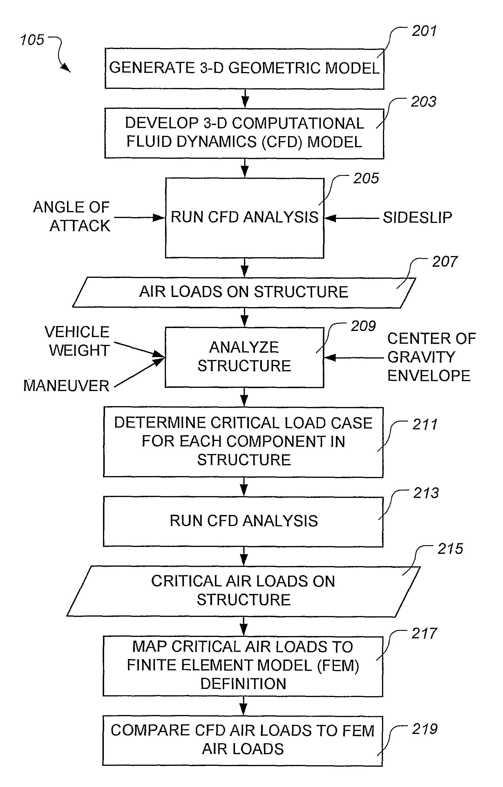
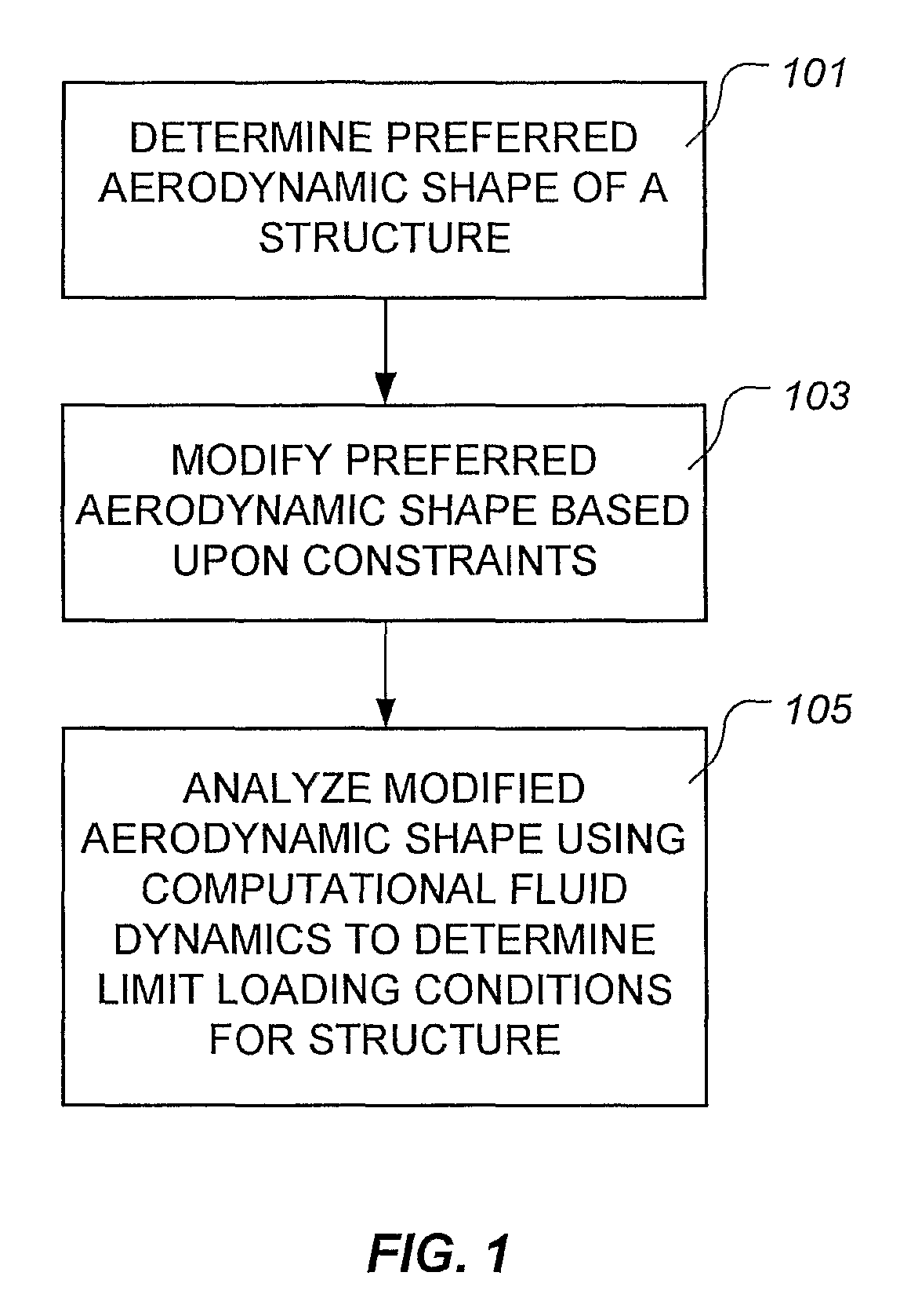
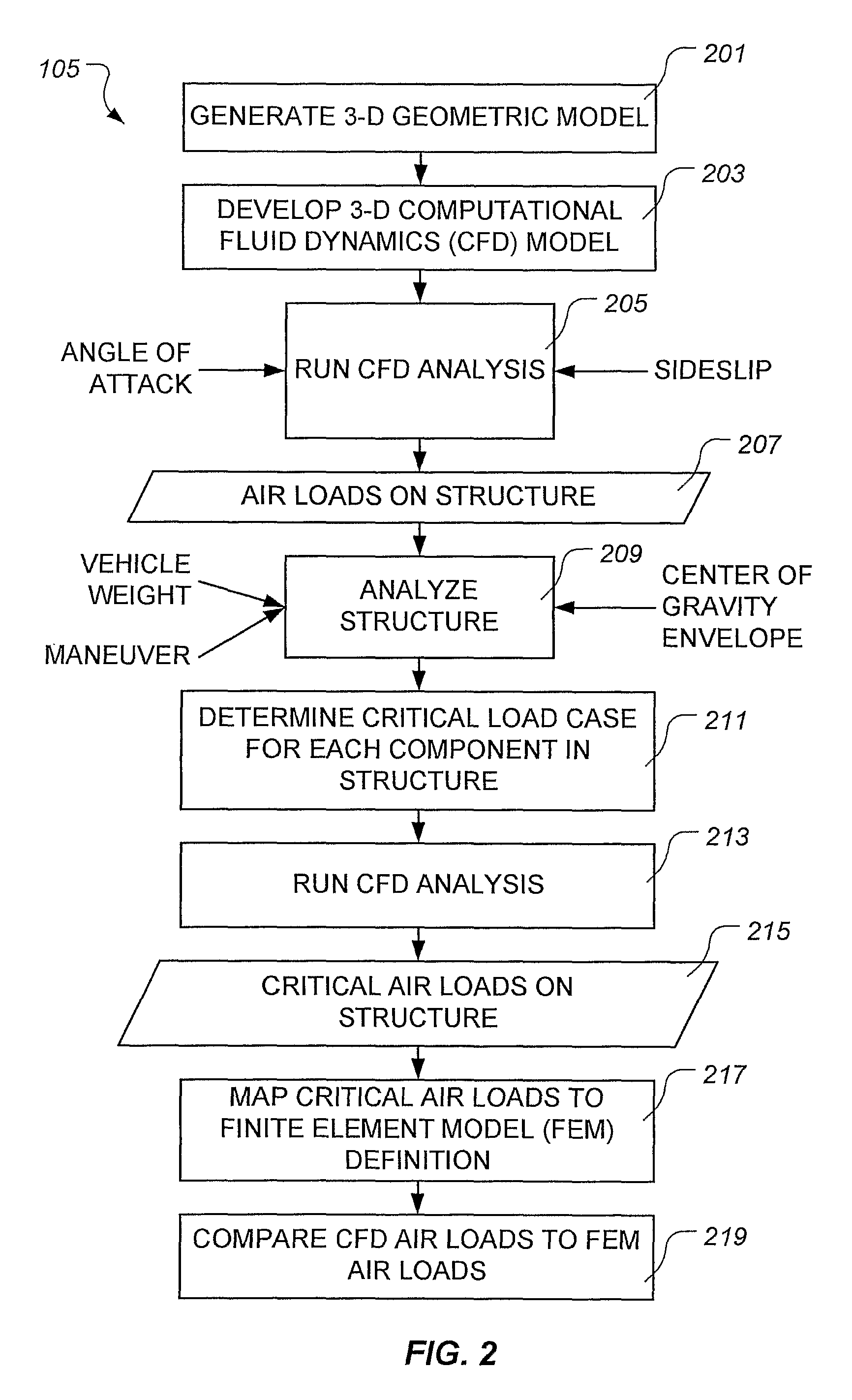
[0018]The present invention represents a method for designing a flight vehicle using “aerodynamic” computational fluid dynamics (CFD) and aircraft flight dynamics. Generally, CFD is the use of computers to analyze problems in fluid dynamics, wherein a continuous fluid is treated i...


PUM


Abstract

A method for designing a flight vehicle includes determining a preferred aerodynamic shape of a structure of the vehicle; modifying the preferred aerodynamic shape based upon constraints; and determining, using aerodynamic computational fluid dynamics, limit loading conditions for the modified aerodynamic shape. A computer-implemented system for designing a flight vehicle includes at least one computer operable to determine a preferred aerodynamic shape of a structure of the vehicle; modify the preferred aerodynamic shape based upon constraints; and determine, using aerodynamic computational fluid dynamics, limit loading conditions for the modified aerodynamic shape. Software for designing a flight vehicle, embodied in a computer-readable medium, is operable to, when executed, determine a preferred aerodynamic shape of a structure of the vehicle; modify the preferred aerodynamic shape based upon constraints; and determine, using aerodynamic computational fluid dynamics, limit loading conditions for the modified aerodynamic shape.

Description

TECHNICAL FIELD[0001]The present invention relates to designing flight vehicles. In particular, the present invention relates to a method for designing a flight vehicle using aerodynamic computational fluid dynamics.DESCRIPTION OF THE PRIOR ART[0002]The airframe of a flight vehicle, such as a rotorcraft or a fixed-wing aircraft, is designed based upon, among other things, the expected loads applied to the aircraft during flight. In particular, the airframe must be able to withstand the aerodynamic pressures encountered during the flight envelope. Conventional flight vehicle design methodologies have limitations in aerodynamic scope, the time to determine limit loads in the flight vehicle, and varying techniques in flight maneuver simulations. Conventionally, each maneuver is simulated to determine the critical flight parameters, such as airspeed, limit load factor, or sideslip angle, required by the design criteria. The criteria are not sufficiently specific to result in unique flig...

Claims


Application Information

Patent Timeline
Patent Type & Authority Patents(United States)
IPC IPC(8): G06F17/50G06F7/48G09B9/08
CPCG06F17/5018G06F17/5095G06F2217/16G06F30/15G06F30/23G06F2111/10Y02T90/00
Inventor NARRAMORE, JIM C.KELLY, STACEYMILLIKEN, ROBERT
Owner TEXTRON INNOVATIONS
Why Eureka
Try Eureka