
Noise shield for a launch vehicle

a launch vehicle and noise shield technology, applied in the field of noise, can solve the problems of increasing the cost of a launch vehicle, requiring space, increasing the weight of the launch vehicle, etc., and achieve the effect of reducing the noise traveling

Inactive Publication Date: 2011-03-29
THE BOEING CO
View PDF17 Cites 32 Cited by
  • Summary
  • Abstract
  • Description
  • Claims
  • Application Information

AI Technical Summary

Benefits of technology

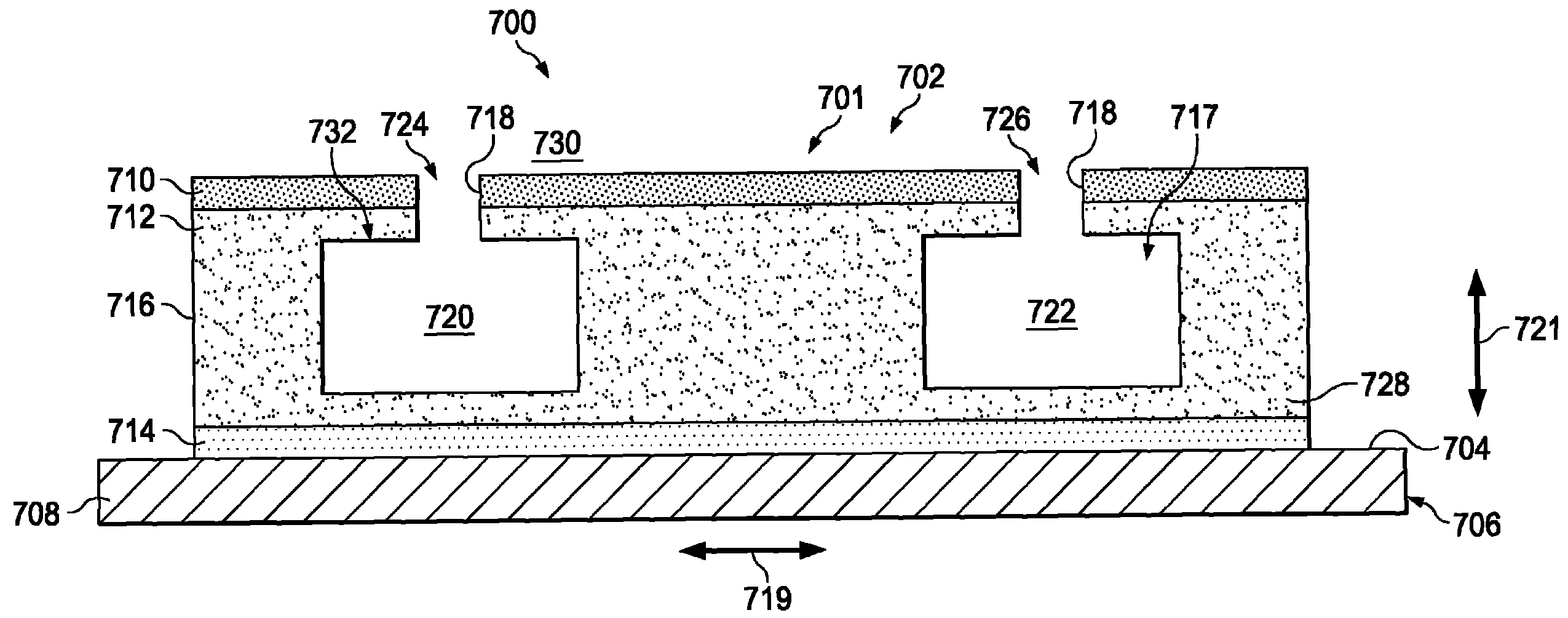
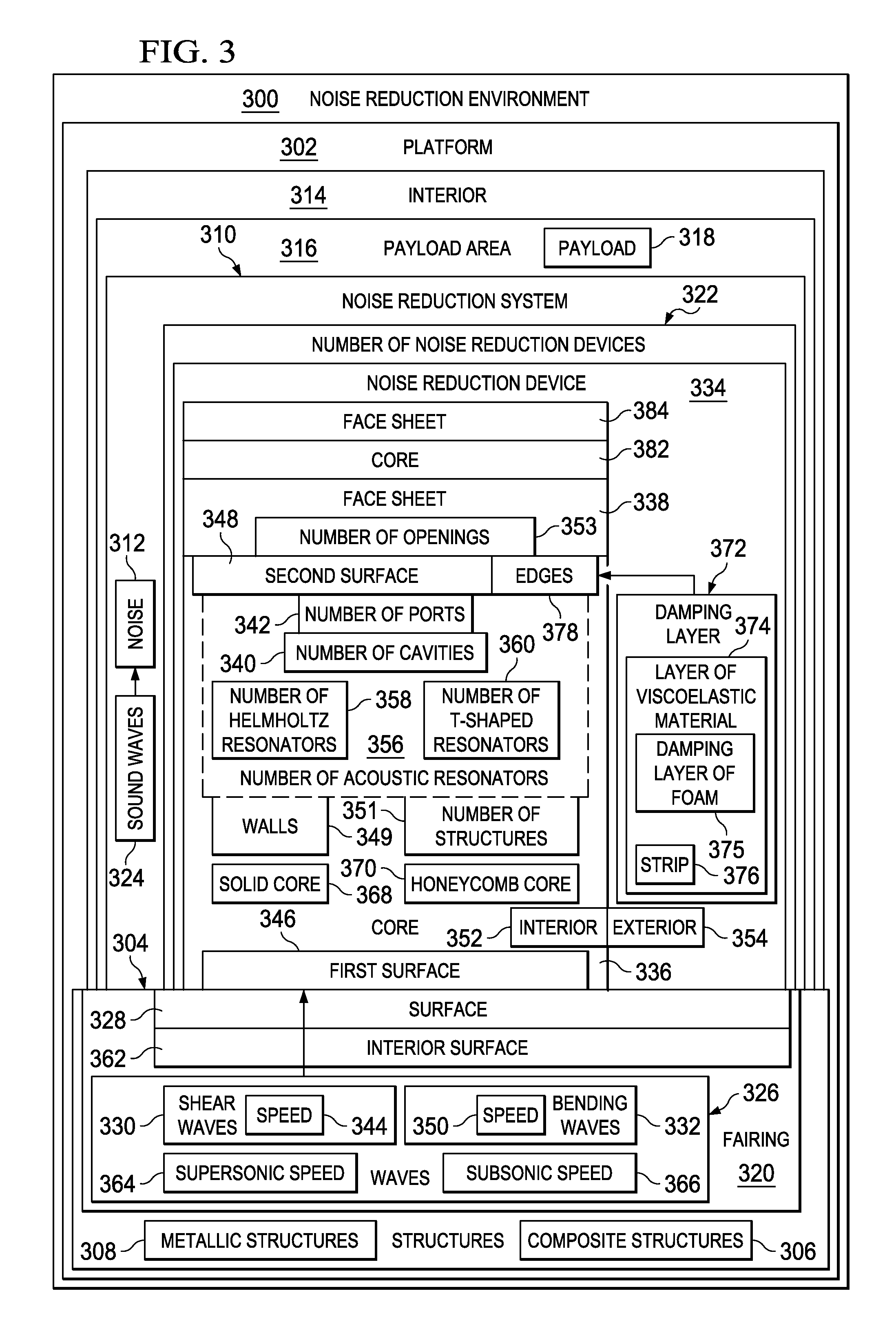
[0010]In one advantageous embodiment, an apparatus comprises a core having a first surface configured for attachment to a surface of a structure, a face sheet located over a second surface of the core, a number of cavities within an interior of the core, and a number of ports for the number of cavities. The number of ports provides communication between the number of cavities within the interior of the core and the exterior of the core. The number of cavities and the number of ports are configured to reduce noise traveling through the core.
[0011]In another advantageous embodiment, a noise reduction system for a launch vehicle comprises a core, a face sheet, and a number of acoustic resonators in the interior of the core. The core has a first surface configured for attachment to a surface of a fairing for the launch vehicle. The face sheet is located over a second surface of the core. The number of acoustic resonators is configured to reduce noise traveling through the core.
[0012]In yet another advantageous embodiment, a method is present for reducing noise. A structure is identified for noise reduction. A number of noise reduction devices is attached to the structure in which each noise reduction device in the number of noise reduction devices comprises a core, a face sheet, a number of cavities within an interior of the core, and a number of ports for the number of cavities. The core has a first surface configured for attachment to a surface of the structure. The face sheet is located over a second surface of the core. The number of ports provides communication between the number of cavities within the interior of the core and the exterior of the core. The number of cavities and the number of ports are configured to reduce the noise traveling through the core.

Problems solved by technology

These types of components, however, require space and increase the weight of the launch vehicle.
Additionally, these systems also increase the cost of a launch vehicle.

Method used


Image

  • Noise shield for a launch vehicle
  • Noise shield for a launch vehicle
  • Noise shield for a launch vehicle

Examples


Embodiment Construction

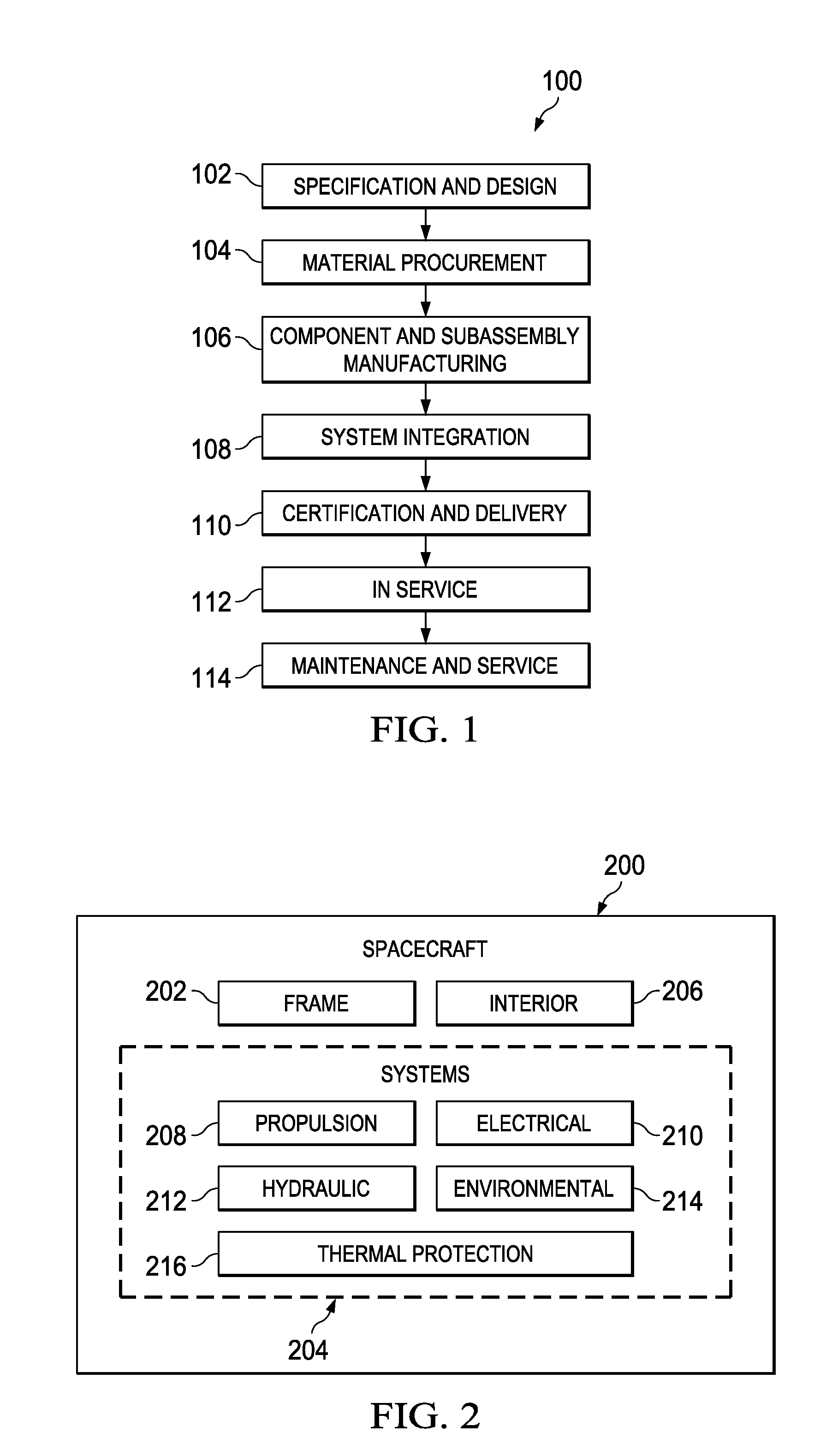
[0027]Referring more particularly to the drawings, embodiments of the disclosure may be described in the context of spacecraft manufacturing and service method 100 as shown in FIG. 1 and spacecraft 200 as shown in FIG. 2. Turning first to FIG. 1, an illustration of a spacecraft manufacturing and service method is depicted in accordance with an advantageous embodiment. During pre-production, spacecraft manufacturing and service method 100 may include specification and design 102 of spacecraft 200 in FIG. 2 and material procurement 104.

[0028]During production, component and subassembly manufacturing 106 and system integration 108 of spacecraft 200 in FIG. 2 takes place. Thereafter, spacecraft 200 in FIG. 2 may go through certification and delivery 110 in order to be placed in service 112. While in service 112 by a customer, spacecraft 200 in FIG. 2 is scheduled for maintenance and service 114, which may include modification, reconfiguration, refurbishment, and / or other maintenance or ...


PUM


Abstract

An apparatus comprises a core having a first surface configured for attachment to a surface of a structure, a face sheet located over a second surface of the core, a number of cavities within an interior of the core, and a number of ports for the number of cavities. The number of ports provides communication between the number of cavities within the interior of the core and the exterior of the core. The number of cavities and the number of ports are configured to reduce noise traveling through the core.

Description

BACKGROUND INFORMATION[0001]1. Field[0002]The present disclosure relates generally to noise and, in particular, to reducing noise radiated by a structure. Still more particularly, the present disclosure relates to a method and apparatus for reducing noise radiated by composite and metallic structures of a launch vehicle.[0003]2. Background[0004]A launch vehicle is used to carry a payload from the surface of the earth into outer space. A launch vehicle may take the form of a rocket, a space shuttle, or some other suitable vehicle that is capable of carrying the payload into outer space. The payload may be, for example, a satellite or some other object that may be carried into outer space. This object may be, for example, an electronics system, a person, or some other suitable object.[0005]With respect to operating a launch vehicle, noise generated by the launch vehicle is a concern in carrying a payload. When the launch vehicle takes the form of a rocket, a fairing may be used to enc...

Claims


Application Information

Patent Timeline
IPC IPC(8): E04B1/82
CPCG10K11/172B64G2001/228B64G1/228
Inventor MATHUR, GOPAL PRASAD
Owner THE BOEING CO
Learn More