Backplane connector with improved pin header

a backplane connector and pin header technology, applied in the direction of two-part coupling devices, connection contact member materials, coupling device connections, etc., can solve the problems of compromising signal integrity, limiting contact density and connector size, and unsatisfactory interference or cross talk between adjacent signal contacts. , to achieve the effect of simple design

Active Publication Date: 2011-03-29
MOLEX INC
View PDF56 Cites 31 Cited by
  • Summary
  • Abstract
  • Description
  • Claims
  • Application Information

AI Technical Summary

Benefits of technology

[0006]It is an object of the present invention to provide an electrical connector which has a relatively simple design and in which differential signal pairs of electrical contacts are effectively isolated by an air dielectric medium from signal contacts of adjacent or nearby differential signal pairs.
[0007]Another object is to provide an electrical connector as characterized above in which the connector housing has a one-piece molded construction and the air dielectric isolation of signal contacts is achieved without materially affecting the structural integrity of the connector.
[0008]A further object is to provide a pin header electrical connector of the above kind which has uniformly spaced electrical contacts adapted for economical manufacture and versatile usage.

Problems solved by technology

Often, the signal contacts are so closely spaced that undesirable interference or cross talk can occur between adjacent signal contacts.
Cross talk occurs when one signal contact induces electrical interference in an adjacent contact due to the overlapping of electrical fields, thereby compromising signal integrity.
Shields, however, take up valuable space within the connector that could otherwise be used to provide additional signal contacts, and thus limit contact density and connector size.
Shields also increase the cost of manufacture of the connector.
While it is known to use air gaps between signal contacts to enhance electrical isolation of adjacent contacts, the utilization of air gaps can: compromise the structural integrity of the connector or complicate the design of the connector by requiring a multiplicity of terminal supporting frames or wafers, as well as increase the physical size of the connector.

Method used


Image

  • Backplane connector with improved pin header
  • Backplane connector with improved pin header
  • Backplane connector with improved pin header

Examples


Embodiment Construction

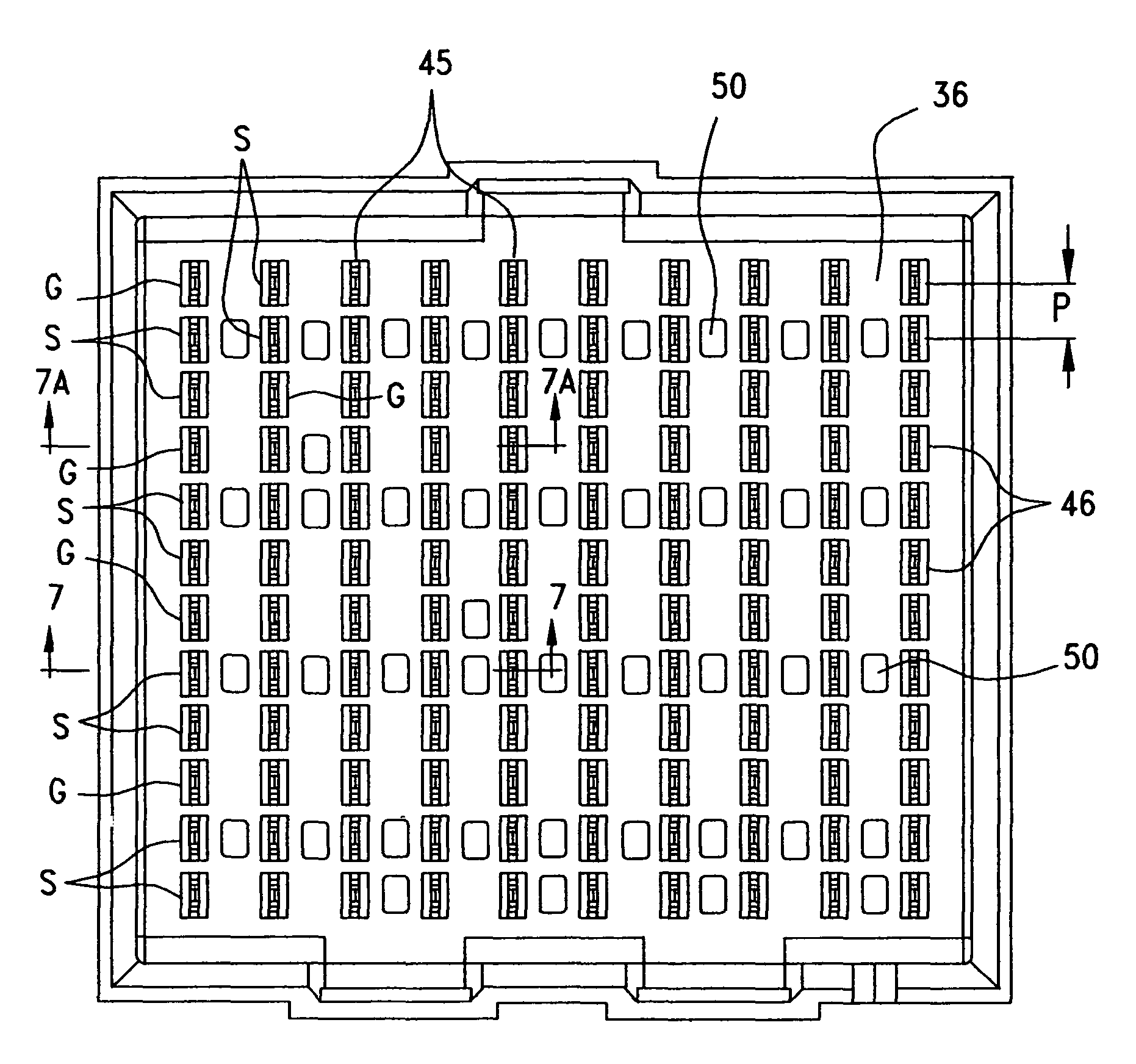
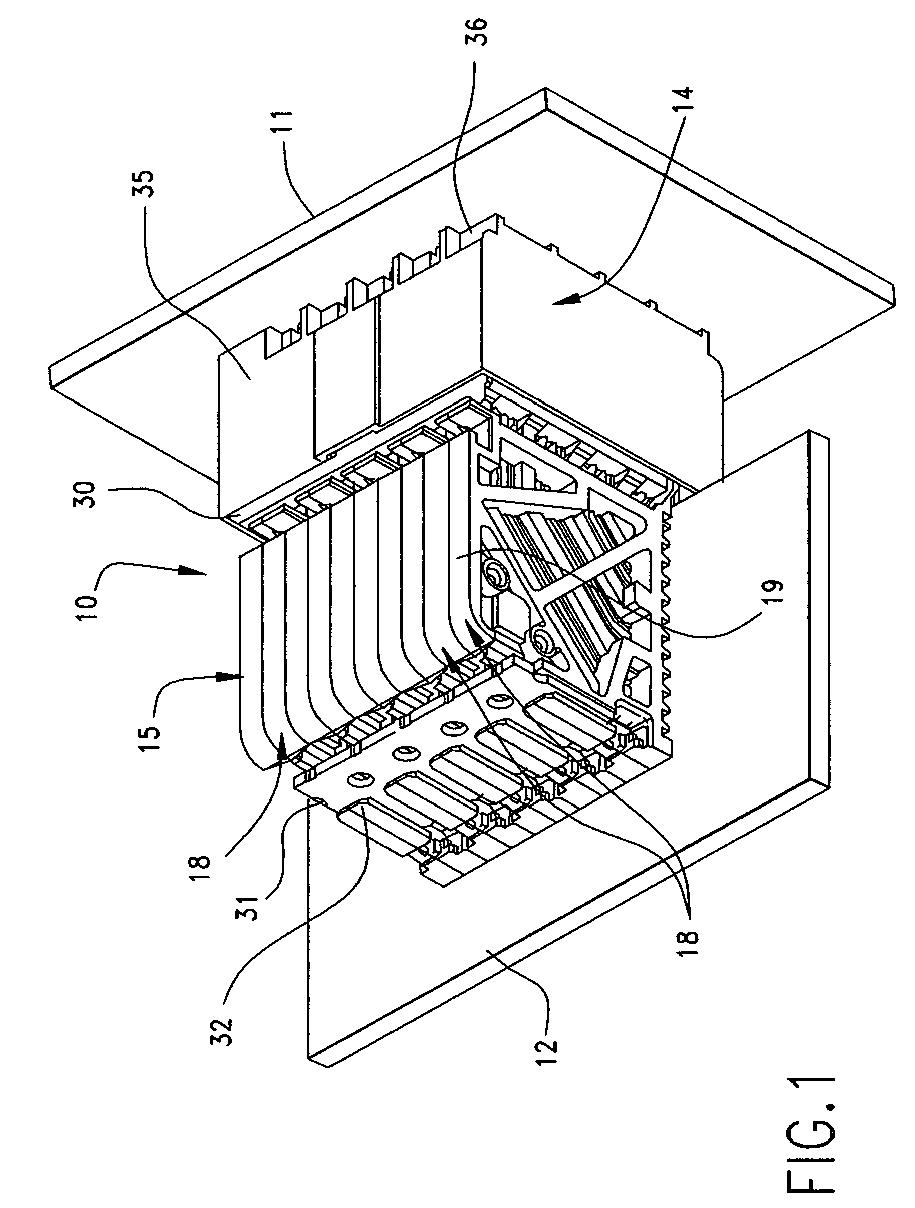
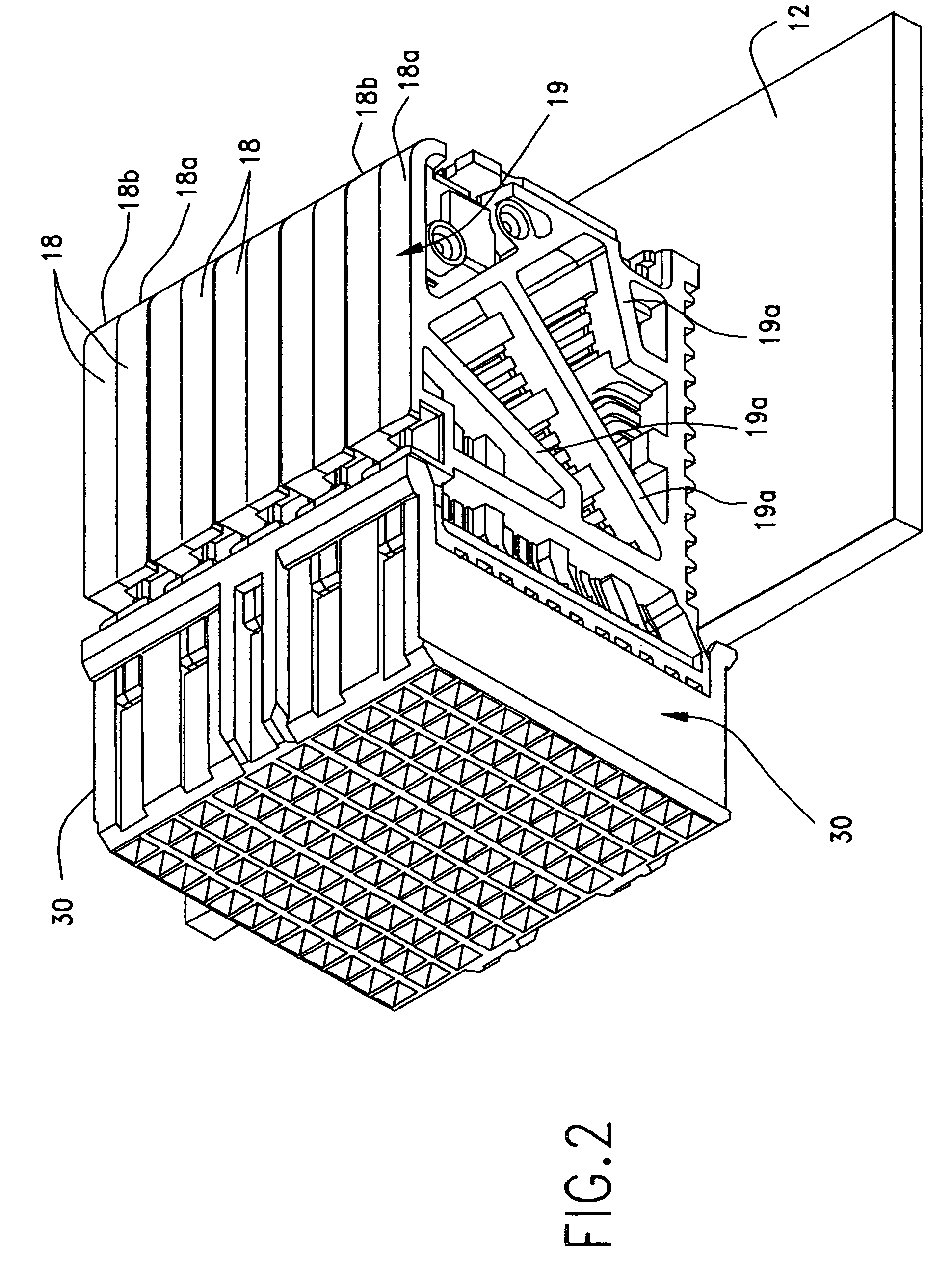
[0024]Referring now more particularly to the drawings, there is shown an illustrative backplane connector 10 in accordance with the invention for electrically connecting a printed circuit board (PCB) board in the form of a backplane 11 and a daughter PCB card 12. The backplane connector 10 includes a backplane pin header connector 14 mounted on the backplane 11 and a daughter card connector 15 mounted on the daughter card 12, which, as illustrated, are plugged together. Because the backplane 11 and daughter card 12 are arranged at a right angle to each other, the backplane connector 10 is a right angle connector and the electrical paths through connector accordingly change direction or bend 90°. However, it will be understood that in other embodiments, the backplane and daughter card can be arranged at other angles to each other, or parallel to each other, and the electrical paths can be arranged accordingly.

[0025]The daughter card connector 15 in this case comprises a plurality of ...


PUM


Abstract

A backplane electrical connector having a pin header that includes a one-piece housing supporting a plurality of columns of edge coupled differential signal pairs of contacts each separated by a ground contact. The pin header housing base is formed with a plurality of air passageways extending through the base, including an air passageway disposed between each signal contact in one column and an immediately adjacent signal contact in an adjacent column for electrically isolating the adjacent signal contacts from each other by an air dielectric medium. Core-outs which extend only partially through the housing base are provided between each signal contact and an adjacent ground contact in an adjacent column for further isolating differential signal pairs.

Description

REFERENCE TO RELATED APPLICATIONS[0001]This application claims the domestic benefit of U.S. Provisional Application Ser. No. 60 / 936,386, filed on Jun. 20, 2007, which disclosure is hereby incorporated by reference.BACKGROUND OF THE INVENTION[0002]The present invention relates generally to electrical connectors, and more particularly to electrical connectors which comprise differential signal pairs of electrical contacts that are designed for high speed electronic communication.[0003]Electrical connectors provide signal connections between electronic devices using signal contacts. Often, the signal contacts are so closely spaced that undesirable interference or cross talk can occur between adjacent signal contacts. Cross talk occurs when one signal contact induces electrical interference in an adjacent contact due to the overlapping of electrical fields, thereby compromising signal integrity. With electronic device miniaturization and high speed electronic communication becoming more...

Claims


Application Information

Patent Timeline
Patent Type & Authority Patents(United States)
IPC IPC(8): H01R4/66H01R13/648H01R12/71H01R24/58
CPCH01R13/6471H01R12/737H01R23/688H01R12/716H01R12/724H01R13/6585H01R12/00
Inventor AMLESHI, PEEROUZLAURX, JOHN
Owner MOLEX INC
Why Eureka
Try Eureka