Landscaping blocks for forming retaining walls and method of producing landscaping blocks

Active Publication Date: 2011-04-05
HERITAGE BLOCK
View PDF13 Cites 12 Cited by
  • Summary
  • Abstract
  • Description
  • Claims
  • Application Information

AI Technical Summary

Benefits of technology

[0006]The present invention provides a landscaping block set used for forming a retaining wall. In one embodiment of the present invention the block set includes at least two groups of precast landscaping blocks. One group of the landscaping blocks includes a depth greater than the depth of the other group. When forming the retaining wall, the group of precast landscaping blocks having the greatest depth is utilized to form one or more lower courses of the retaining wall. Stacked on top of t

Problems solved by technology

There are, however, a number of drawbacks and disadvantages to natural stone.
Thus there are substantial expenses involved in mining natural stone, handling the stone and transporting the stone sometimes as far as country to country.
In addition, laying natural stone is time consuming and expensive.
This is because natural stone is not uniform in shape and size.
Natural stone is difficult to lay in a mortar base and even more difficult to lie in a dry stack.
Further compounding the problem is that skilled stone laying tradesmen are difficult to find and when they are located, they too are expensive.
Again, this is expensive and time consuming.

Method used


Image

  • Landscaping blocks for forming retaining walls and method of producing landscaping blocks
  • Landscaping blocks for forming retaining walls and method of producing landscaping blocks
  • Landscaping blocks for forming retaining walls and method of producing landscaping blocks

Examples


Embodiment Construction

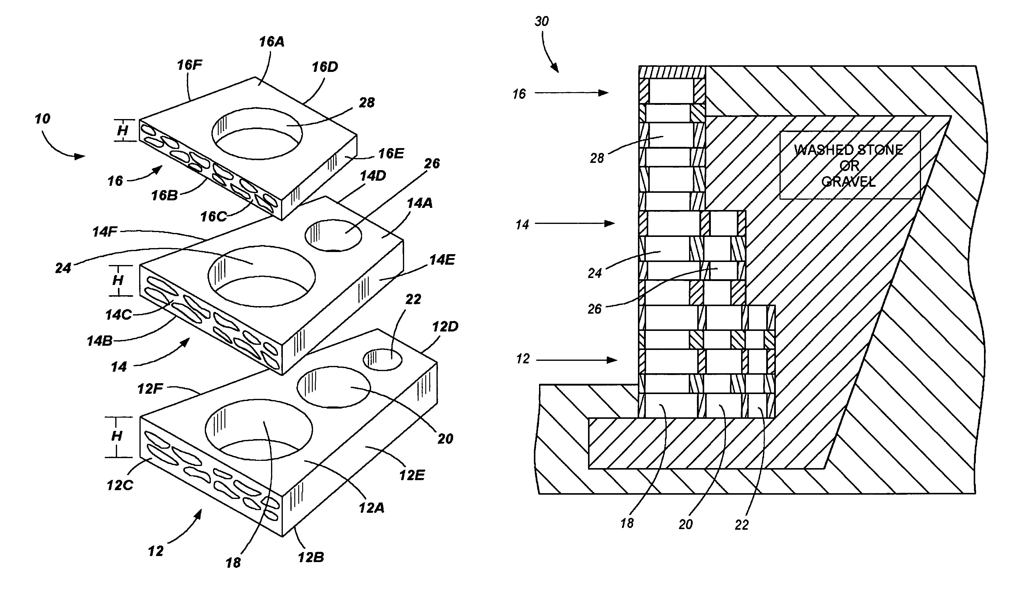
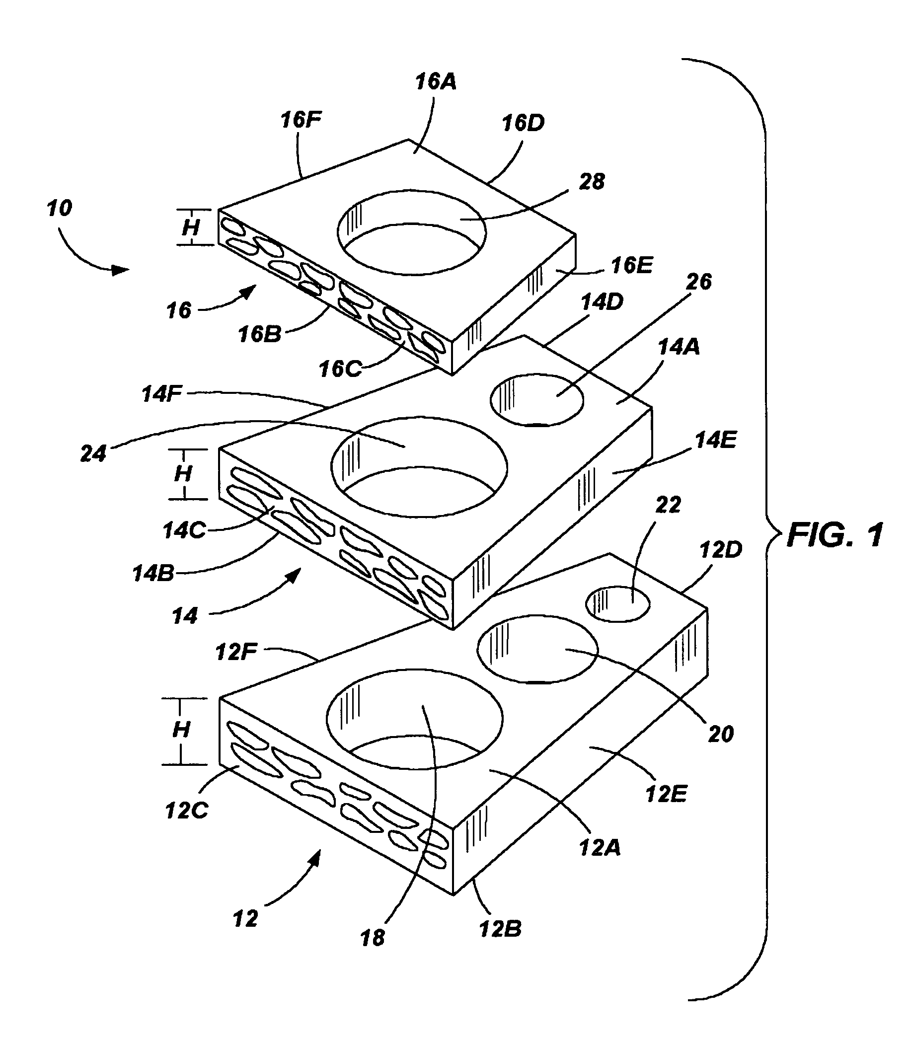
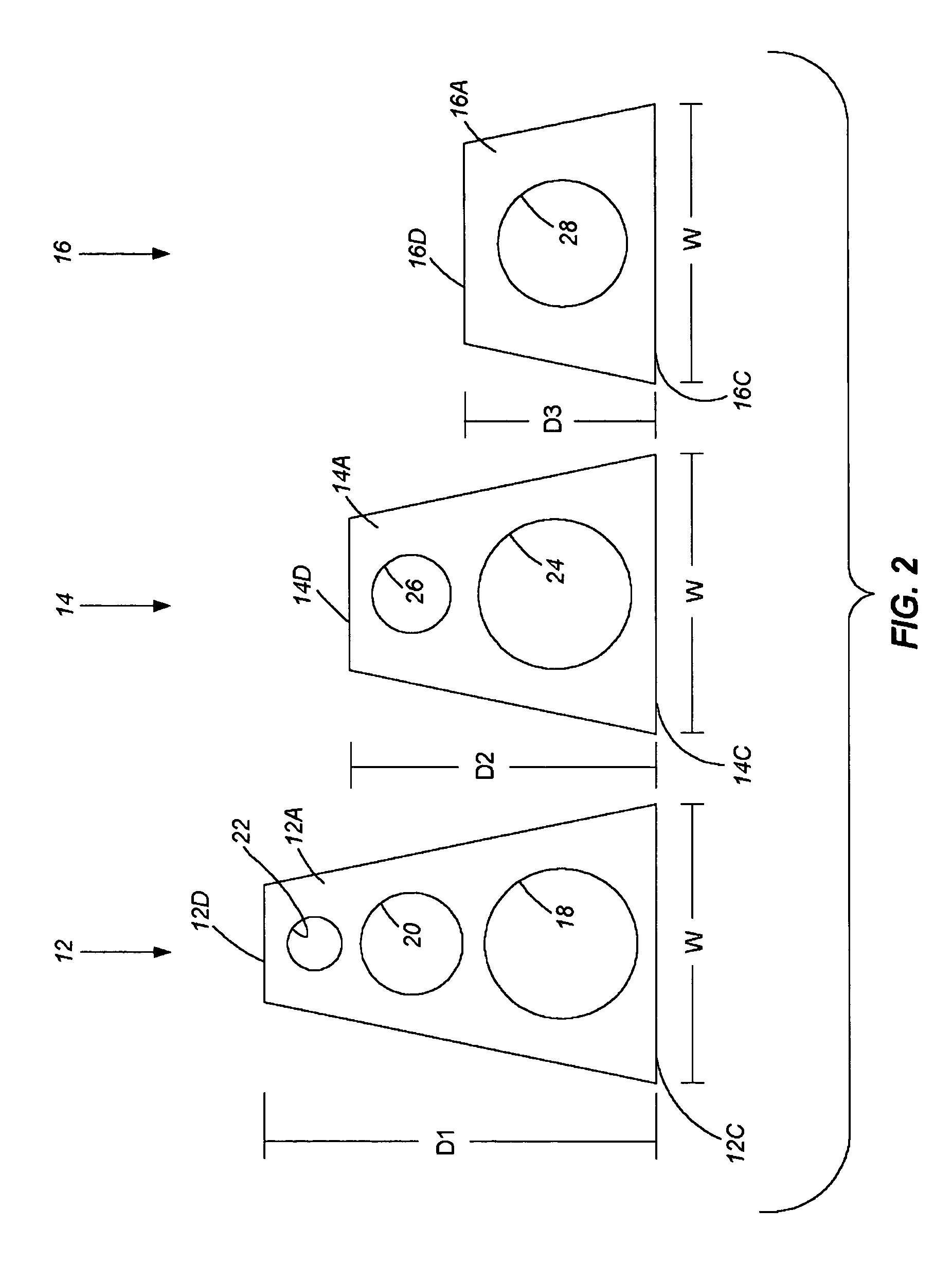
[0019]With further reference to the drawings, particularly FIGS. 1-4, the present invention is shown therein and comprises a set of precast concrete landscaping blocks. The set of landscaping blocks is referred to generally by the numeral 10. In the case of one embodiment, the set of precast concrete landscaping blocks 10 comprises a first group of blocks 12, a second group of blocks 14, and a third group of blocks 16. As seen in FIGS. 1 and 2, the three groups of blocks 12, 14, and 16 are of a different size. More particularly, each block of each group includes a depth. The depth of the blocks of the first group is referred to as D1, the depth of the blocks of the second group 14 is referred to as D2, and the depth of the third group of blocks 16 is referred to as D3. Further, each block includes a width W and a height H. In some embodiments, the height of the blocks can vary. In one set of blocks, the height of the individual blocks could be 3 inches, 4½ inches, and / or 6 inches.

[0...


PUM


Abstract

A set of landscaping blocks is provided for building a retaining wall. The set of landscaping blocks include three groups of precast blocks with each group being of a different size and particularly having a different depth. The group of blocks having the greatest depth is utilized to form one or more lower courses of the retaining wall. The group of blocks having the second greatest depth is utilized to form one or more intermediate courses for the retaining wall, and the intermediate courses of block are stacked over the one or more lower courses of block. Finally, the group of blocks having the least depth is utilized to form one or more upper courses of the retaining wall. Once the retaining wall is formed, a backside of the retaining wall assumes a step configuration wherein portions of the upper surfaces of the lower and intermediate courses are exposed. To form the blocks of each group, concrete is poured into a mold having a series of side-by-side sections. Disposed in each section of the mold is a molded surface having a stone design formed therein. Thus, at least one face of each block formed in each section of the mold includes a molded face that conforms to the design of the molded surface.

Description

FIELD OF THE INVENTION[0001]The present invention relates to precast landscaping blocks, and more particularly to precast concrete blocks that include a molded face that simulates natural stone and which can be dry stacked one on top of the other to form a retaining wall.BACKGROUND OF THE INVENTION[0002]Natural stones are used in landscaping residential and commercial buildings. For example, natural stone can be utilized to form planters, retaining walls, curbing or edging. There are, however, a number of drawbacks and disadvantages to natural stone. First, natural stone must be mined, packaged and transported. Often to obtain certain types of stone, the natural stone must be transported long distances. Thus there are substantial expenses involved in mining natural stone, handling the stone and transporting the stone sometimes as far as country to country.[0003]In addition, laying natural stone is time consuming and expensive. This is because natural stone is not uniform in shape an...

Claims


Application Information

Patent Timeline
IPC IPC(8): E02D29/02
CPCB28B7/0044B28B7/007E02D29/0266B28B7/245E02D29/025B28B7/18
Inventor SIVER, MARK A.SIVER, WAYNE P.HANSEN, JEFFERY L.
Owner HERITAGE BLOCK
Why Eureka
Try Eureka