Ez key registration assembly

a key and assembly technology, applied in the field of keys, can solve the problems of common mispositioning between the clamped position of the original key and the clamped position of the key blank to be cut, and achieve the effects of reducing cutting vibration, minimizing misalignment, and reducing error-pron

Inactive Publication Date: 2011-04-05
KABA ILCO CORP
View PDF11 Cites 43 Cited by
  • Summary
  • Abstract
  • Description
  • Claims
  • Application Information

AI Technical Summary

Benefits of technology

[0009]This invention provides for proper positioning of the key with respect to the vise by providing inter-fitting indexing features on a jaw and on the key. These indexing features prevent the key from being mispositioned with respect to the jaw such that when the jaws are tightened towards each other and the keys are clamped in position, there can be no mispositioning between the original key and the key blank.
[0016]Alternatively, each vise jaw may consist of a pair of spaced apart jaw portions, which each engage opposite end portions of the key and which have an opening therebetween providing access to the working edge or edges of the key. By forming the vise jaws as spaced apart jaw portions, the key can be supported at its head end and at its tip end while being securely clamped in position. This double clamping of the key at both the head and tip end can have the advantageous effect of reducing cutting vibration in the key blade during cutting.
[0017]It is therefore an object of this invention to provide a less error-prone method and apparatus for securing keys in key cutting machines.
[0018]It is a further object of this invention to provide an improved method and apparatus for properly positioning keys in a key cutting apparatus to minimize misalignment between the bitted key and the key blank to be bitted.

Problems solved by technology

Unfortunately experience has shown that these prior systems often result in miscut keys.
This is almost always due to a mispositioning of either the original key or of the key blank in its clamp vise.
It is, however, common in known clamping systems, whether they clamp at the blade, head, shank, or combinations thereof, that mispositioning between the clamped position of the original key and the clamped position of the key blank to be cut is a common problem.

Method used


Image

  • Ez key registration assembly
  • Ez key registration assembly
  • Ez key registration assembly

Examples


Embodiment Construction

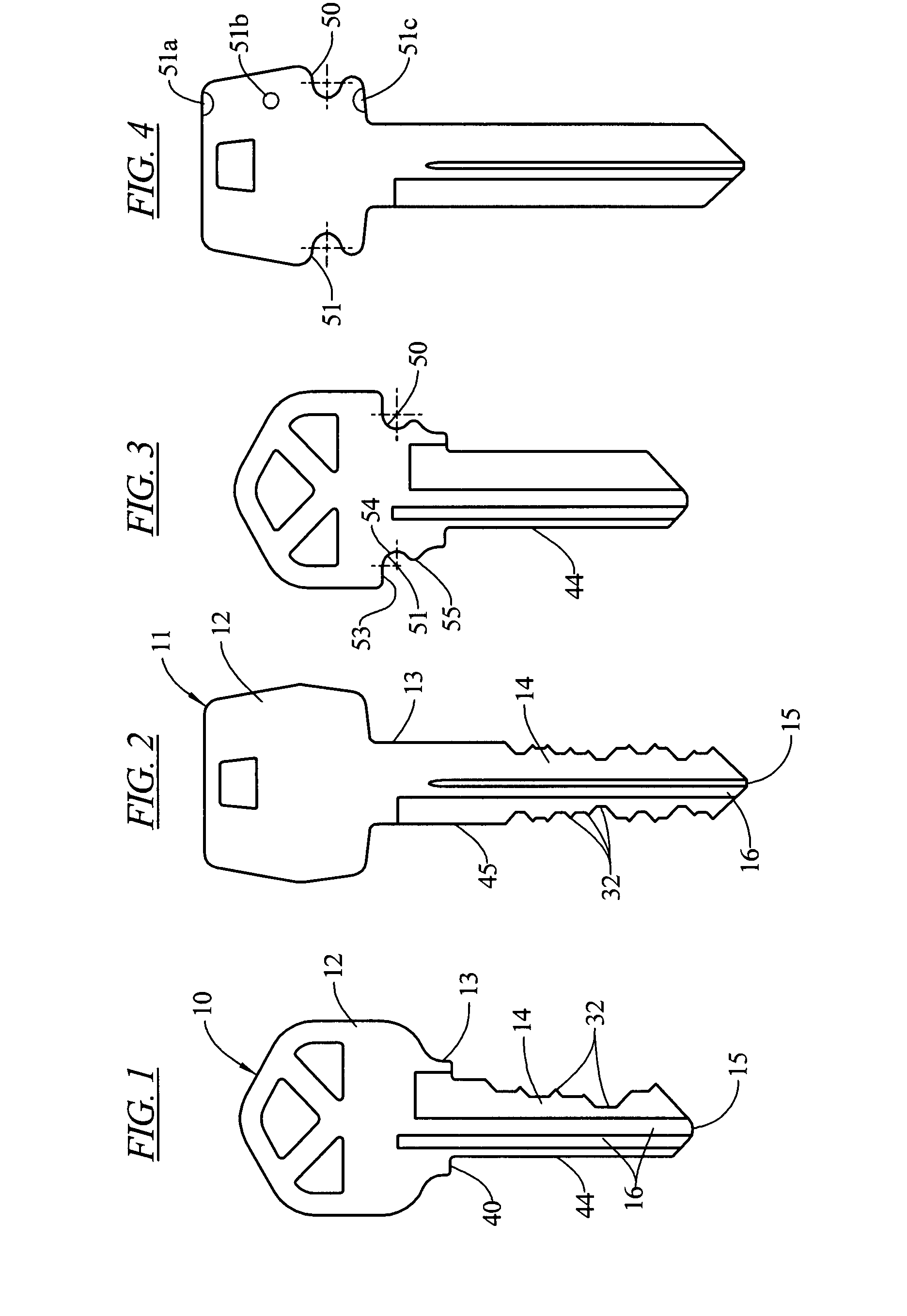
[0034]Shown in FIGS. 1 and 2 a key 10 or 11 may generally be described as having a head portion 12, a shank portion 13, a blade 14, and a tip 15. The blade portion may be provided with grooves, raised ribs, or other wards 16 that inter-fit with corresponding ward configurations in the key slot of the lock. As is well known, the features 16 are usually formed by milling or stamping subsequent during manufacture of the key blank.

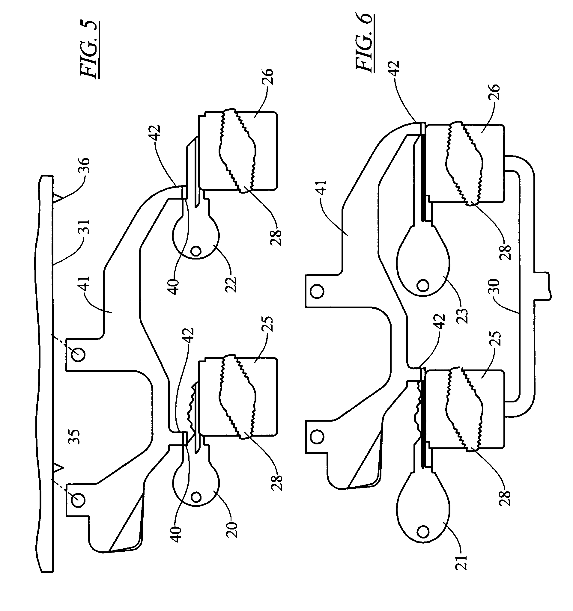
[0035]As is illustrated in FIGS. 5 and 6, when it is desired to duplicate an existing key 20 or 21, a key blank 22, 23 is provided that has the same key blade wards 16 as the original key 20, 21. Both the original key 20 and the key blank are then positioned in vises 25-26, which are spaced apart a predetermined distance. The vises 25, 26 include opposed relatively moveable jaws, and may be equipped with a headed bolt 28 or the like for tightening the jaws of the vise together to clamp the keys 20-22 or 21-23 in their respective positions. The vises may be com...


PUM

PropertyMeasurementUnit
thicknessaaaaaaaaaa
surface featuresaaaaaaaaaa
lengthaaaaaaaaaa

Abstract

A locating system and method for accurately positioning key blanks with respect to a key cutter where the key head is clamped between opposing jaws with the key blade working edges projecting therefrom, the key head is provided with shaped recesses having at least a partially specifically shaped edge wall and wherein at least one jaw member is provided with a projection having a correspondingly shaped sidewall, the pin being positioned with respect to the clamp such that when the key blank head is abutted against the pin with the key blank edge configuration mating to the pin sidewall configuration, the key blade will project from the jaw in a proper position for engagement by either the bitting follower or bitting cutter respectively.

Description

FIELD OF THE INVENTION[0001]This invention relates to keys, and more particularly to a key cutter and key head configuration utilizing projecting clamp pins and key head wall configurations mating with the pins for properly positioning the key in the jaw clamp and to methods of aligning keys in key cutting machines.BACKGROUND OF THE INVENTION[0002]Edge bitted key blanks are normally cut by cutting machines which preposition the key blank in a jawed clamp or vise. The positioning holds the edge of the key blade which is to be cut for bitting a fixed position relative to a clamped original key.[0003]Most often the keys are positioned with respect to either the tip end of the blade or to a shoulder at the head end of the blade since bitting measurements along the length of the blade are normally specified as having their positions at specified distances from one of those two base points, i.e. either the blade tip or the blade shoulder. Precise positioning of the key edge is critical to...

Claims


Application Information

Patent Timeline
Patent Type & Authority Patents(United States)
IPC IPC(8): B23C3/35
CPCB23C3/355Y10S269/909Y10T409/308736Y10T409/303752Y10T409/309016Y10T409/300952
Inventor BELFLOWER, JOSEPH F.LAWSON, KERMITMOREHART, GARY E.DAVIS, DOUG G.
Owner KABA ILCO CORP
Why Eureka
Try Eureka