
Method for application and accurate positioning of graphics on a surface

a technology of surface and graphics, applied in the field of graphics application and accurate positioning, can solve the problem that none of the known devices and methods provide all, and achieve the effect of accurate positioning, accurate application and positioning

Active Publication Date: 2011-04-12
THE BOEING CO
View PDF35 Cites 24 Cited by
  • Summary
  • Abstract
  • Description
  • Claims
  • Application Information

AI Technical Summary

Benefits of technology

[0010]This need for an apparatus and method for application and accurate positioning of graphics and a graphics positioning device on a surface that does not have the problems associated with known devices and methods, as well as a unique, nonobvious, and advantageous apparatus and method, is satisfied. None of the known devices and methods provide all of the numerous advantages discussed herein. Unlike known devices and methods, an embodiment of the apparatus and method for application and accurate positioning of graphics and a graphics positioning device on a surface may provide one or more of the following advantages: the method is faster than known methods and may be 2-3 times, or more, faster than adhesive methods; the method provides for decreased labor costs, does not require masking, de-masking, or re-masking steps, and is accurate with very fast curing; the method and apparatus provide a better finish quality, greater durability and more artistic flexibility and complexity compared to known methods and devices; the method and apparatus provide a positioning system to accurately position the graphics and graphics positioning apparatus on large surface areas that may have approximately cylindrical curvature and contours, as well as offset from or raised above such large surface areas; the method and apparatus enables efficient application of graphics over approximately 80% of an aircraft exterior that is considered decorative, such as the fuselage, vertical tail, rudder, and wings; the method and apparatus provide for graphics and images in a digitalized, electronic form until actually applied to the aircraft, thus enabling easily made last minute changes; the method and apparatus provide the integration of a graphics application device and a precision positioning system, which together can be used to apply complex graphics or images to a contoured surface; and, the method and apparatus of the invention may be used with aircraft, rotorcraft, vehicles such as automobiles and trucks, watercraft such as boats and ships, and various other applications for which application of graphic images to large contoured surfaces is desired.
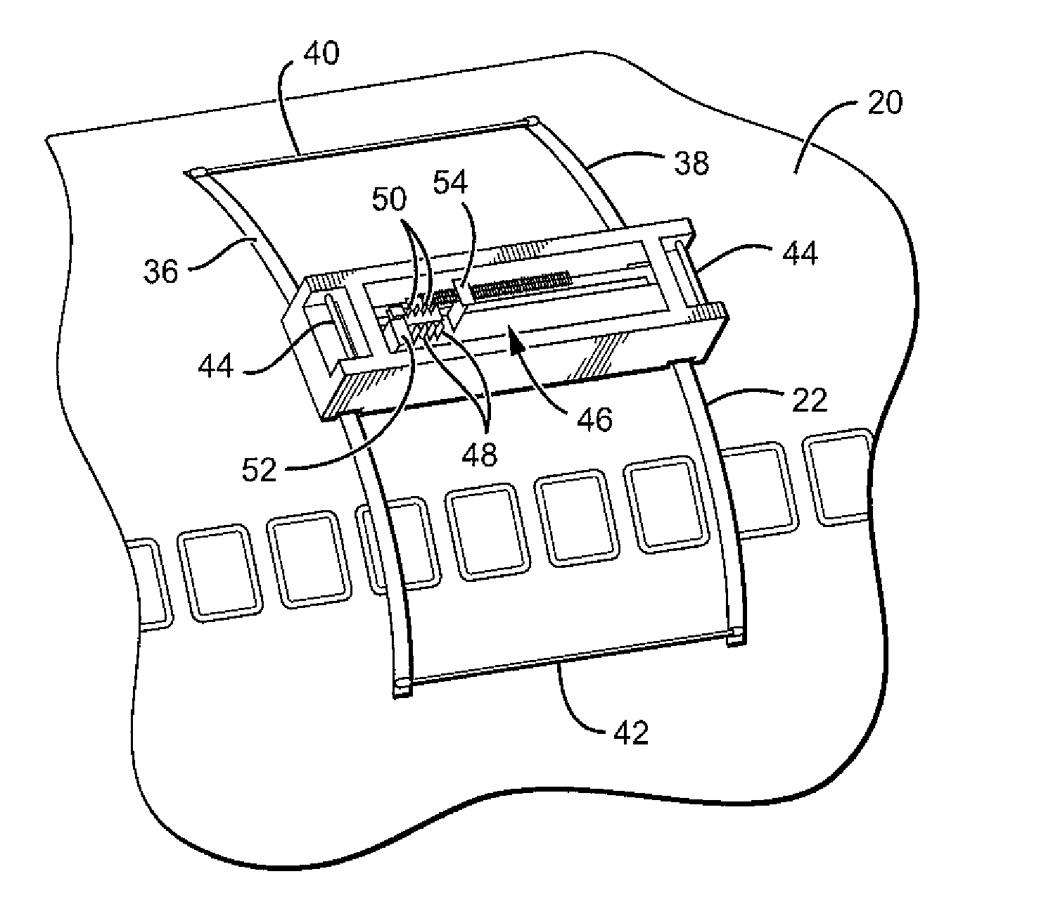
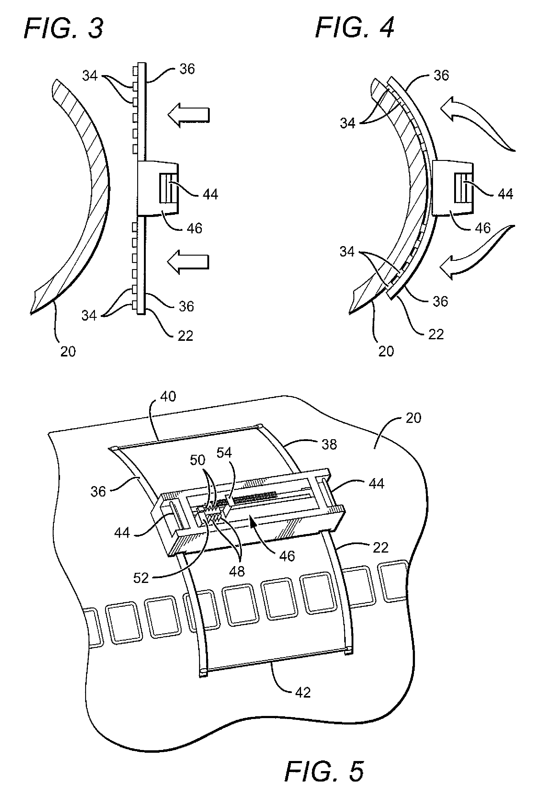
[0012]In another embodiment of the invention, there is provided a method of applying and accurately positioning at least one graphic image on a large contoured surface, comprising the steps of: connecting a flexible-rail positioning system with an attached paint application system to a portion of the surface to be painted or decorated; identifying reference marks on the portion of the surface to be painted or decorated; aligning the paint application system to the reference marks on the portion of the surface to be painted or decorated; aligning a selected segment of the graphic image to be applied to the reference marks on the portion of the surface to be painted or decorated; applying the selected segment of the graphic image by moving the paint application system along the portion of the surface to be painted or decorated using a flexible rail; and, detaching the flexible-rail positioning system after the graphic image is applied, and moving the flexible-rail positioning system to another portion of the surface.
[0013]In another embodiment of the invention, there is provided a method of accurately applying and positioning a graphic image on an exterior surface of an aircraft, comprising the steps of connecting a flexible-rail positioning system with an attached graphic image application system to a portion of the surface; identifying reference marks on the portion of the surface; aligning the graphic image application system to the reference marks on the portion of the surface; aligning a selected segment of the graphic image to be applied to the reference marks on the portion of the surface; applying the selected segment of the graphic image by moving the graphic image application system along the portion of the surface using the flexible-rail positioning system, and, detaching the flexible-rail positioning system after the graphic image is applied, and moving the flexible-rail positioning system to another portion of the surface.

Problems solved by technology

None of the known devices and methods provide all of the numerous advantages discussed herein.

Method used


Image

  • Method for application and accurate positioning of graphics on a surface
  • Method for application and accurate positioning of graphics on a surface
  • Method for application and accurate positioning of graphics on a surface

Examples


Embodiment Construction

[0022]Embodiments of the invention now will be described more fully hereinafter with reference to the accompanying drawings, in which some, but not all embodiments of the invention are shown. Indeed, several different embodiments may be provided and should not be construed as limited to the embodiments set forth herein. Rather, these embodiments are provided so that this disclosure will be thorough and complete and will fully convey the scope of the invention to those skilled in the art. Like numbers refer to like elements throughout.

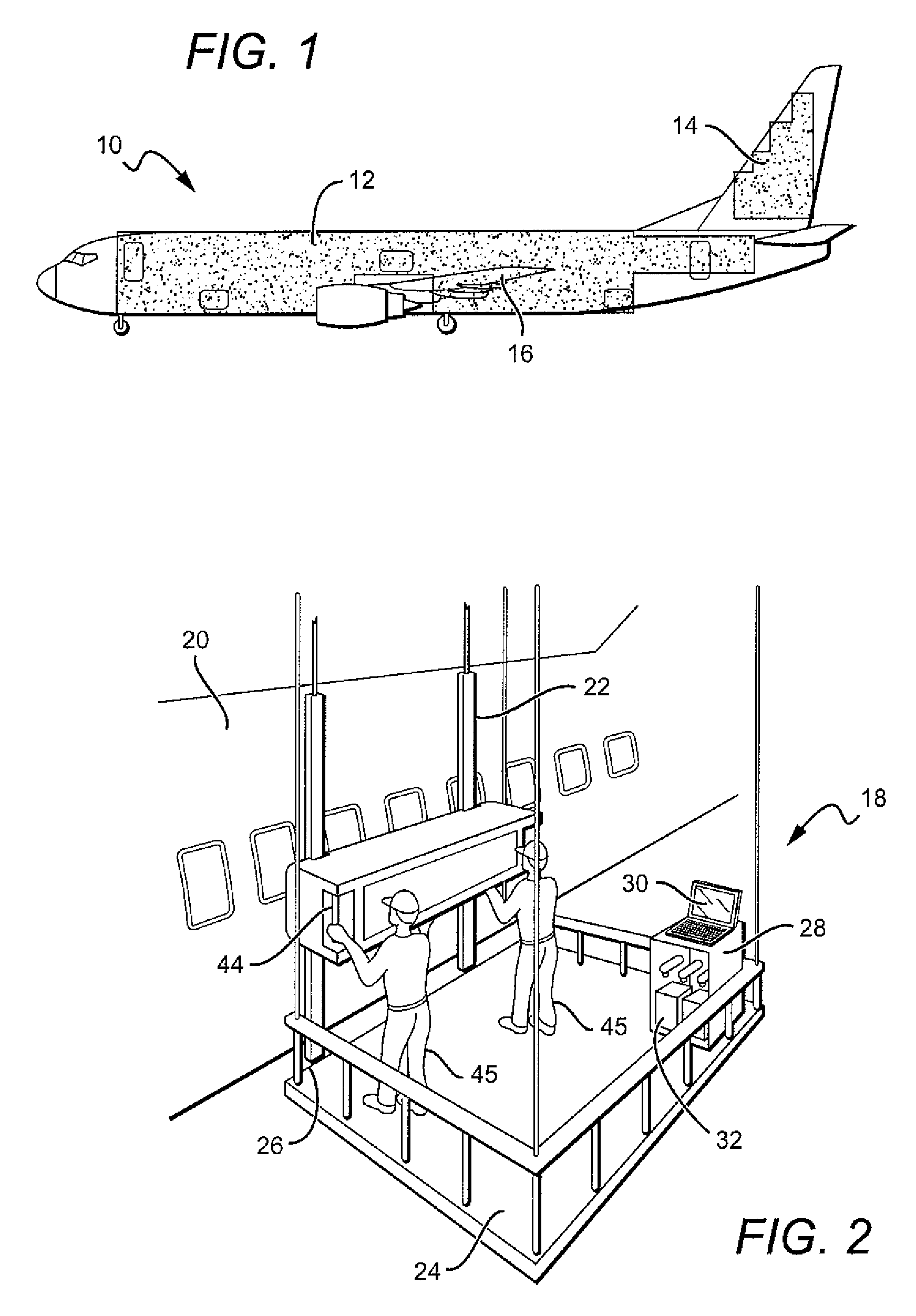
[0023]Referring now to the drawings, FIG. 1 is a side view of an airplane 10 in which the shaded areas are those surfaces on which graphic images may be applied with the apparatus and method of the invention. Such areas include, but are not limited to, a fuselage surface 12, a tail surface 14, and a wing surface 16. The apparatus and method of the invention may be used for applying graphic images to aircraft, rotorcraft, vehicles such as automobiles and...


PUM


Abstract

There is provided a method of applying an accurately positioning at least one graphic image on a large contoured surface using an apparatus comprising a flexible-rail positioning system mounted on a portion of the surface on which the graphic image is to be applied, a graphic image application system, software to operate the positioning system, and software to operate the graphic image application system.

Description

BACKGROUND OF THE INVENTION[0001]1) Field of the Invention[0002]An apparatus and method for application and accurate positioning of graphics on a surface is provided. More particularly, an apparatus and method for application and accurate positioning of graphics and for accurate positioning of a graphics application device on a contoured surface is provided.[0003]2) Description of Related Art[0004]For various commercial products, it is desirable to apply colorful visual graphics through the application of a pigmented formulation to a surface to form an aesthetically pleasing image. The graphics may be applied to the surface by various known methods, including applying a paint material to the surface by means of a brush or a spray. Other known methods may be used that do not use painting processes. Such methods may include adhering to a surface an applique or decal having the desired graphics or images formed thereon.[0005]The foregoing known methods have been used to apply visual gr...

Claims


Application Information

Patent Timeline
Patent Type & Authority Patents(United States)
IPC IPC(8): B41J3/407B05B13/04B41J3/36
CPCB41J3/4073B41J25/308B41J11/002B23Q2210/008B41J11/00214
Inventor BAIRD, RICHARD W.BUTTRICK, JAMES N.DALBY, GLENN R.STUDLEY, SILAS L.
Owner THE BOEING CO
Learn More