Cap apparatus for liquid jetting head and liquid jetting apparatus

a technology of liquid jetting head and cap apparatus, which is applied in printing and other directions, can solve the problems of decreased workability and difficulty in accommodating the cap inside the cap holder, and achieve the effect of reducing the resistance at the time of accommodating the cap in the cap holder, sucking efficiently unnecessary liquid, and improving assembly workability

Active Publication Date: 2011-04-12
BROTHER KOGYO KK
View PDF17 Cites 3 Cited by
  • Summary
  • Abstract
  • Description
  • Claims
  • Application Information

AI Technical Summary

Benefits of technology

[0008]In view of this, an object of the present invention is to improve an assembling workability of a cap apparatus for a liquid jetting head.
[0045]According to the second aspect of the present invention, the insertion resistance at the time of accommodating the cap in the cap holder is reduced substantially, and the assembling workability is improved. Moreover, since the liquid jetting apparatus has the suction unit which generates the negative pressure, it is possible to suck efficiently the unnecessary liquid. At this time, since the cap apparatus has the absorber, it is possible to absorb assuredly the liquid sucked in the cap.

Problems solved by technology

However, at the time of assembling a cap apparatus, since a cap is inserted into a cap holder while a surrounding wall of the cap makes a close contact with a surrounding wall of the cap holder, air between a sealed space generated between a bottom wall of the cap and a bottom wall of the cap holder is compressed, and an insertion resistance is developed, and it is difficult to accommodate the cap inside the cap holder.
Due to this, an operator has to assemble the cap by forcing into the cap holder while avoiding a close contact with the cap holder by bending the surrounding wall of the cap, and workability is declined.

Method used


Image

  • Cap apparatus for liquid jetting head and liquid jetting apparatus
  • Cap apparatus for liquid jetting head and liquid jetting apparatus
  • Cap apparatus for liquid jetting head and liquid jetting apparatus

Examples


first embodiment

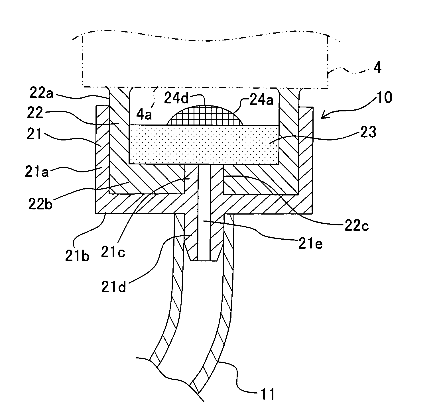
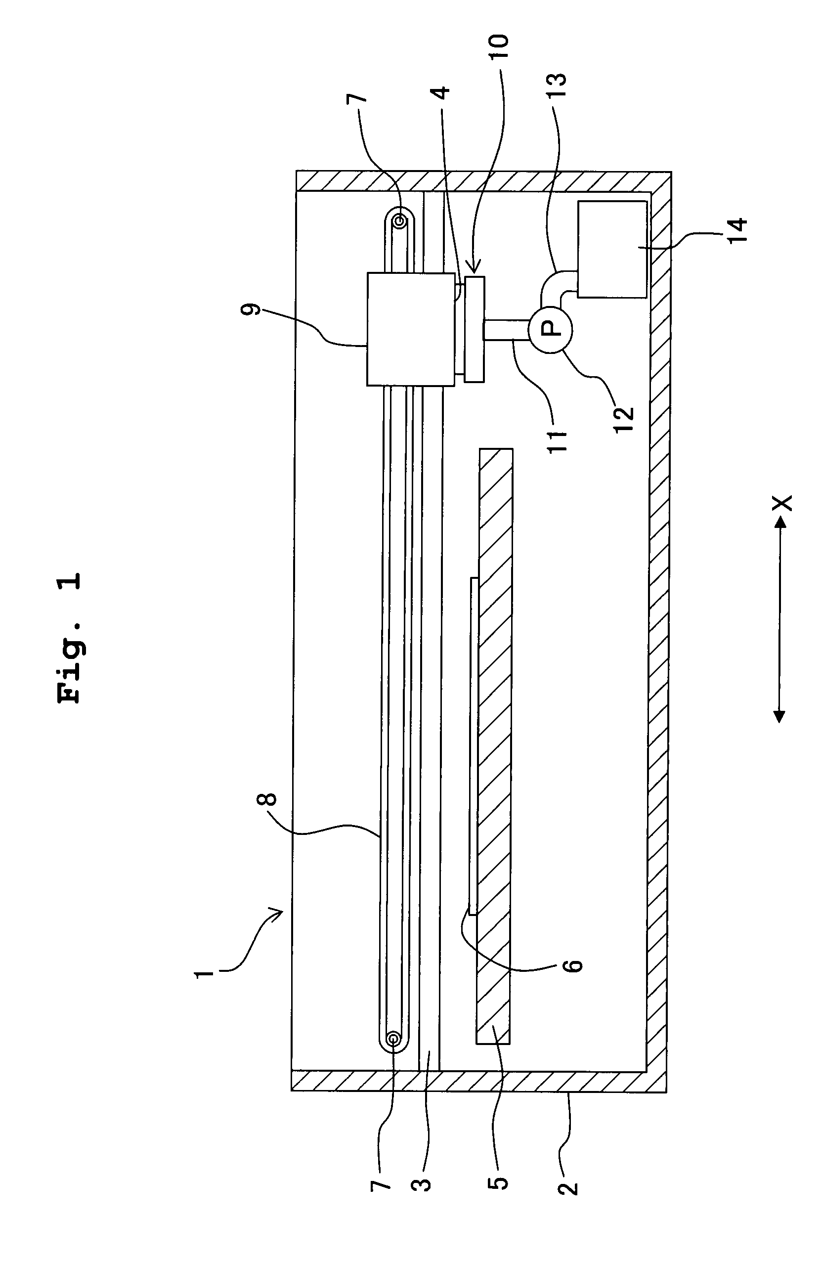
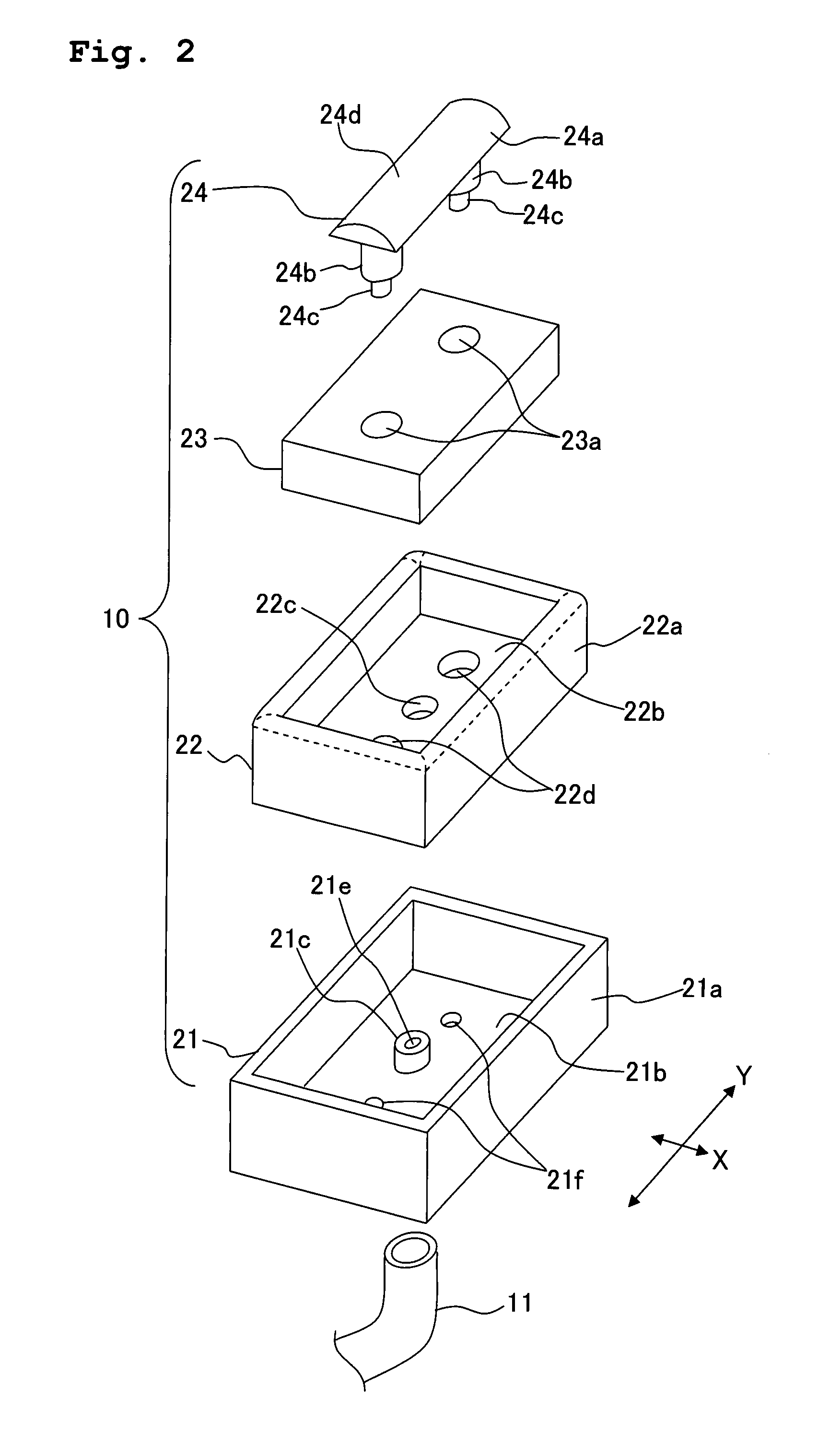
[0067]FIG. 1 is a schematic cross-sectional view of an ink-jet printer (liquid jetting apparatus) according to a first embodiment of the present invention. As shown in FIG. 1, the ink-jet printer 1 includes a guide rod 3 which is installed in a casing 2, and a carriage 9 is slidably supported on the guide rod 3. An ink-jet head 4 (liquid jetting head) is provided on a bottom portion of the carriage 9, such that a nozzle surface 4a in which a nozzle hole 4b is formed is exposed downward (refer to FIG. 6). Moreover, a platen 5 is arranged on a lower side of the carriage 9, and a recording body 6 (such as a paper) is transported on the platen 5 by a paper feeding mechanism (not shown in the diagram), and an ink is jetted toward the recording body 6 from the ink-jet head 4. The carriage 9 is joined to a timing belt 8 which is put around a pair of pulleys 7, and the timing belt 8 is arranged parallel to an axial direction of the guide rod 3. A motor (not shown in the diagram) which drive...

second embodiment

[0085]Next, a second embodiment of the present invention will be described below. FIG. 7A is a cross-sectional view showing the state before fixing a holder 31 of a cap apparatus 30 according to the second embodiment, and FIG. 7B is a cross-sectional view after fixing the holder 31. Since a structure of the cap apparatus 30, except for the holder 31, is similar as the structure of the cap apparatus 10 in the first embodiment, same reference numerals are assigned to the components same as in the first embodiment, and detailed description of these components is omitted. As shown in FIG. 7A, the holder 31 has a holding body 31a which has a cross-sectional arc shaped projecting portion 31d, in contact with an upper surface of the absorber 23, a pin 31b which is protruded downward from the holding body 31a, and an engaging portion 31e having an arrowhead shape, which is provided at a lower end of the pin 31b. Specifically, the engaging portion 31e has a shaft portion 31c having a diamete...

third embodiment

[0088]Next, a third embodiment of the present invention will be described below. FIG. 8 is a cross-sectional view of a cap apparatus 40 according to the third embodiment. FIG. 9 is a perspective view of a holder 41 of the cap apparatus 40 shown in FIG. 8. Since a structure of the cap apparatus 40, except for the holder 41 is similar as the structure of the cap apparatus 10 in the first embodiment, same reference numerals are assigned to the components same as in the first embodiment, and detailed description of these components is omitted. As shown in FIG. 8 and FIG. 9, the holder 41 has a holding body 41a which makes a contact with the upper surface of the absorber 23, a pair of pins 41b which are projected downward from the holding body 41a, and an engaging portion 41c which is provided on a lower end of each pin 41b. The holding body 41a is extended in a longitudinal direction of the absorber 23, and has a triangular upper surface of which a central portion is projected upward in...


PUM


Abstract

A cap apparatus includes a cap which seals nozzles of a liquid jetting head, an absorber which is accommodated tightly inside the cap, a cap holder which is accommodated tightly inside the cap, and a holder which has a holding body which makes a contact with an upper surface of the absorber, a pin which is protruded downward from the holding main portion, and an engaging portion which is provided on a front end of the pin. Through holes which make the cap, the absorber, and the cap holder communicate, are formed in the cap, the absorber, and the cap holder. Since the through holes function as a passage, it is possible to improve an assembling workability of the cap apparatus.

Description

CROSS-REFERENCE TO RELATED APPLICATION[0001]The present application claims priority from Japanese Patent Application No. 2006-280905, filed on Oct. 16, 2006, the disclosure of which is incorporated herein by reference in its entirety.BACKGROUND OF THE INVENTION[0002]1. Field of the Invention[0003]The present invention relates to a cap apparatus for a liquid jetting head, and a liquid jetting apparatus.[0004]2. Description of the Related Art[0005]An ink-jet printer has hitherto been known as an example of a liquid jetting apparatus which jets a liquid from nozzles in a liquid jetting head. In the ink-jet printer, there is a possibility that jetting quality is affected by blocking of nozzles due to mixing of air in an ink, evaporation of an ink solvent, and thickening of ink inside an ink-jet head. Therefore, the ink-jet printer is provided with a cap apparatus for carrying out a purge operation by restoring the nozzles by sucking forcibly the ink from the nozzles of the ink-jet head ...

Claims


Application Information

Patent Timeline
Patent Type & Authority Patents(United States)
IPC IPC(8): B41J2/165
CPCB41J2/16508
Inventor SHINDO, TATSUYAUSUI, TAKAMASA
Owner BROTHER KOGYO KK
Why Eureka
Try Eureka