Key switch sheet and key switch module

a key switch and module technology, applied in the direction of contact, emergency contact, moving contact, etc., can solve the problems of increasing the cost of fixing sheet, and difficulty in processing the fixing sheet, so as to enhance the thinning and manufacturing property of the key switch, and improve the click feeling of the key switch

Inactive Publication Date: 2011-04-12
ORMON CORP
View PDF5 Cites 47 Cited by
  • Summary
  • Abstract
  • Description
  • Claims
  • Application Information

AI Technical Summary

Benefits of technology

[0013]The present invention has been devised to solve the problems described above, and an object thereof is to improve the click feeling of the key switch without adding a new component or a new mechanism, so that the click feeling of the key switch is improved while enhancing thinning and manufacturing property of the key switch and lowering the cost.

Problems solved by technology

In such a key switch, the click feeling of when the key is pushed with the finger becomes an important issue since the stroke of the key is short, and various methods for improving the click feeling have been proposed.
However, in the structure of Patent Document 1, the resin dimple is formed by adding the resin material to the front surface of the fixing sheet fixed with the contact spring, and thus processing of the fixing sheet is difficult.
The cost of the fixing sheet greatly rises even if the resin dimple is processed in the fixing sheet.
Moreover, in the key switch module fabricated in such a manner, a problem in that the resin dimple may drop arises, where the cost further increases if measures are taken to prevent the resin dimple from dropping.
However, in the key switch module as disclosed in Patent Document 1, if a light guide sheet made from soft resin is sandwiched between the fixing sheet and the key, the resin dimple is buried in the light guide sheet when the key is pushed, and consequently, the stroke of the key becomes long and the effect of improving the click feeling significantly lowers.
The key switch module described in Patent Document 2 satisfies both absorption of manufacturing error in positional relationship between the operation member and the contact spring in a operating direction of the contact spring and thinning in the operating direction of the contact spring by arranging the elastic body between the fixing sheet and the sheet-like operation member, but is not aimed to improve the click feeling.
Furthermore, the cost of the key switch module becomes high since an extra member, that is the elastic body, is required.
In addition, the projecting portion barely has the possibility of dropping since the projecting portion is a pressure sensitive adhesive layer.
In addition, the projecting portion barely has the possibility of dropping since the projecting portion is a layer of pressure sensitive adhesive or adhesive.
In addition, the projecting portion barely has the possibility of dropping since the projecting portion is a pressure sensitive adhesive layer.

Method used


Image

  • Key switch sheet and key switch module
  • Key switch sheet and key switch module
  • Key switch sheet and key switch module

Examples


first embodiment

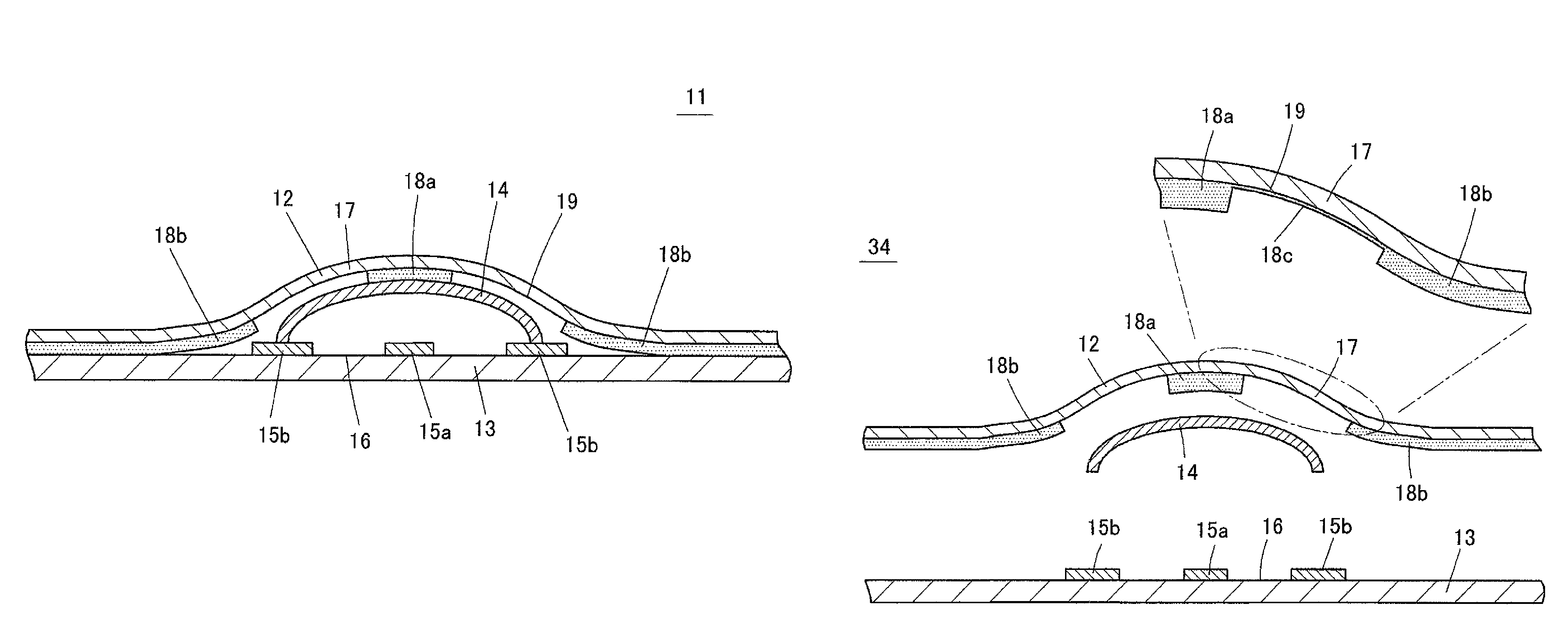
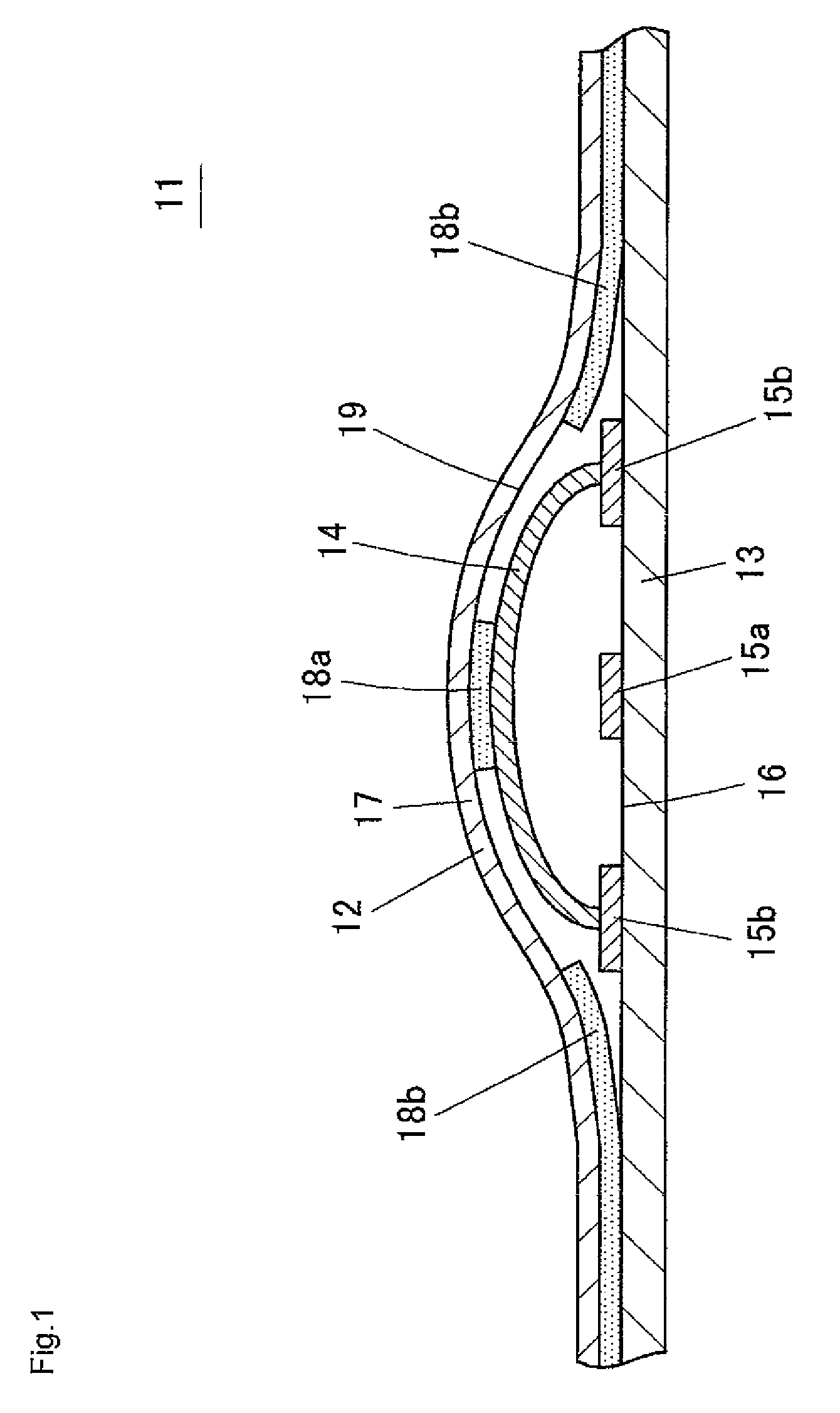
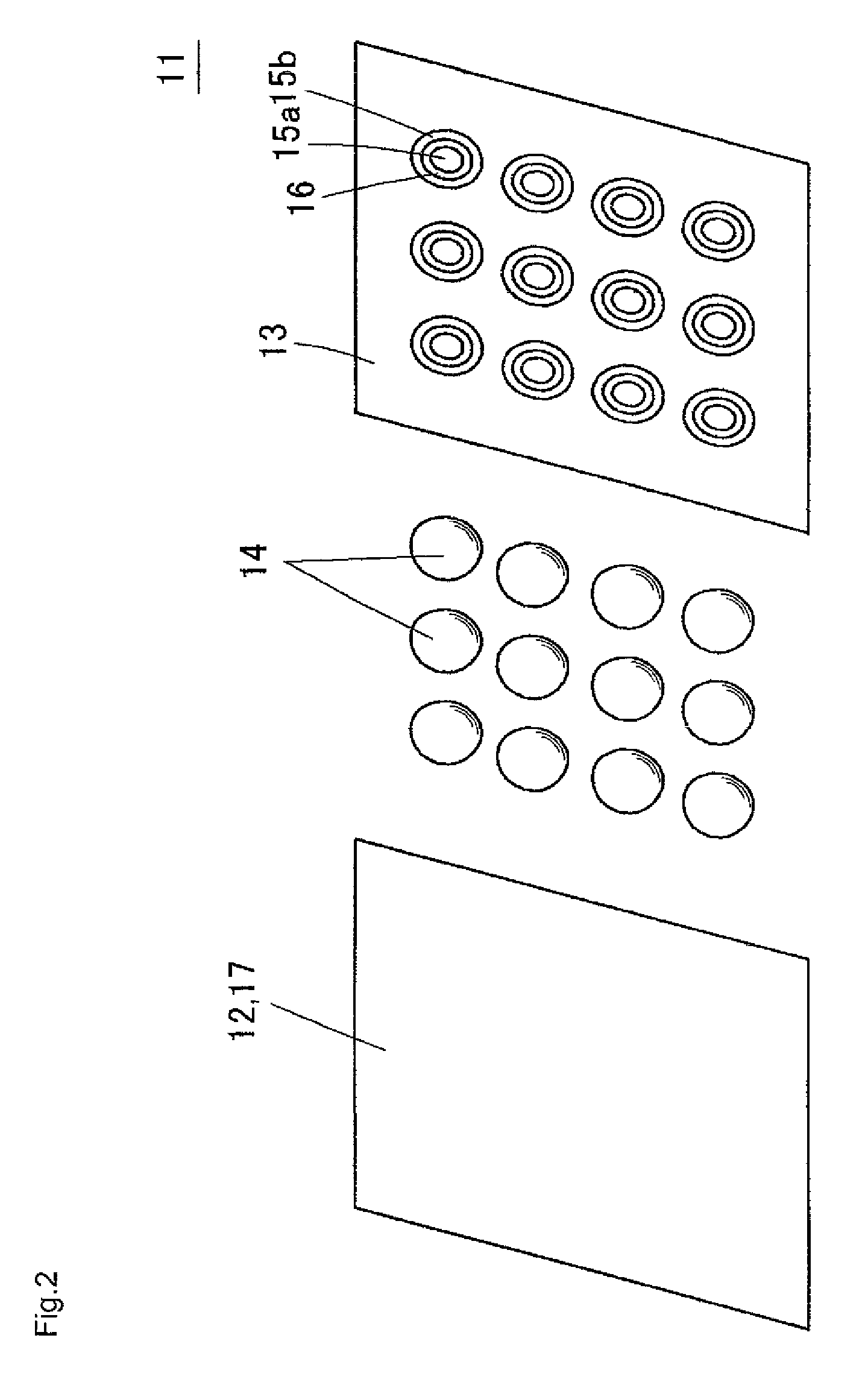
[0069]A key switch module substrate according to a first embodiment of the present invention will be described below with reference to FIGS. 1 to 8. FIG. 1 is a cross-sectional view showing, in an enlarged manner, one part of a key switch module substrate 11 according to the first embodiment, FIG. 2 is an exploded perspective view of the key switch module substrate 11, and FIG. 3 is a rear view of a fixing sheet 12 (key switch sheet) used in the key switch module substrate 11.

[0070]The key switch module substrate 11 according to the first embodiment includes a printed wiring substrate 13 (substrate) including a flexible print substrate, a contact spring 14, and the fixing sheet 12. As shown in FIG. 2, a plurality of circular first contact portions 15a (first fixed contact) made from a conductive material are arrayed on the front surface of the printed wiring substrate 13, and a second contact portion 15b (second fixed contact) is annularly formed around each first contact portion 15...

second embodiment

[0086]FIG. 9 is an exploded cross-sectional view showing a key switch module substrate 34 according to a second embodiment of the present invention. In the present embodiment, the thicknesses of the pressure sensitive adhesive layers of the projecting portion 18a and the substrate pressure sensitive adhesive layer 18b are differed. In particular, the thickness of the projecting portion 18a is desirably thicker than the thickness of the substrate pressure sensitive adhesive layer 18b.

[0087]As a method of differing the thickness of the projecting portion 18a and the thickness of the substrate pressure sensitive adhesive layer 18b, for example, the height of the ridge or the depth of the valley is differed between the surface for applying the projecting portion 18a and the surface for applying the substrate pressure sensitive adhesive layer 18b when forming bumps on the transfer roller 22 with the roll coater method as shown in FIGS. 4A and 4B. Furthermore, the projecting portion 18a ...

third embodiment

[0106]FIG. 12 is a cross-sectional view showing a key switch module substrate 37 according to a third embodiment of the present invention. In the present embodiment, the inner diameter of the substrate pressure sensitive adhesive layer 18b is formed to be slightly smaller than the diameter of the contact spring 14. Therefore, the inner peripheral portion of the substrate pressure sensitive adhesive layer 18b adheres to the bottom portion of the outer periphery of the contact spring 14 in the key switch module substrate 37.

[0107]According to this embodiment, the contact spring 14 is less likely to shift and move when pushed down, or the contact spring 14 is less likely to rise since the inner peripheral portion of the substrate pressure sensitive adhesive layer 18b adhered to the printed wiring substrate 13 is made to adhere to the bottom portion of the contact spring 14.


PUM


Abstract

A key switch sheet has a pressure sensitive adhesive layer for holding a contact spring by adhering to an apex portion of a dome-shaped contact spring at a back surface of a base material sheet. A thickness of the pressure sensitive adhesive layer at a region to be made to adhere to the apex portion of the contact spring is thicker than a thickness of the pressure sensitive adhesive layer at a peripheral region and thicker than or equal to a thickness of the pressure sensitive adhesive layer at a region where the base material sheet is made to adhere to a substrate.

Description

BACKGROUND OF THE INVENTION[0001]1. Technical Field[0002]The present invention relates to a key switch sheet and a key switch module. Specifically, the present invention relates to a key switch module substrate used in a key switch used by being incorporated in a mobile telephone, or the like; a key switch module having a key top arranged on the key switch module substrate; and a key switch sheet for fixing a contact spring of the key switch module substrate.[0003]2. Related Art[0004]In mobile telephones and the like, a key switch having a structure in which a key is pushed with a finger thereby deforming a contact spring underneath, conducting electrode portions by the contact spring and turning ON the switch is used. In such a key switch, a raised dome-shaped contact spring is arranged on a second contact portion formed to surround a first contact portion, the first contact portion is covered by the contact spring while being spaced apart from the first contact portion, and the fr...

Claims


Application Information

Patent Timeline
Patent Type & Authority Patents(United States)
IPC IPC(8): H01H1/10
CPCH01H13/88H01H13/7006H01H2205/018H01H2205/026H01H2229/028H01H2221/006H01H2227/01H01H2227/028H01H2227/032H01H2205/03
Inventor OHSUMI, YOSHIMASA
Owner ORMON CORP
Why Eureka
Try Eureka