Automatic adjustment circuit, and filter circuit

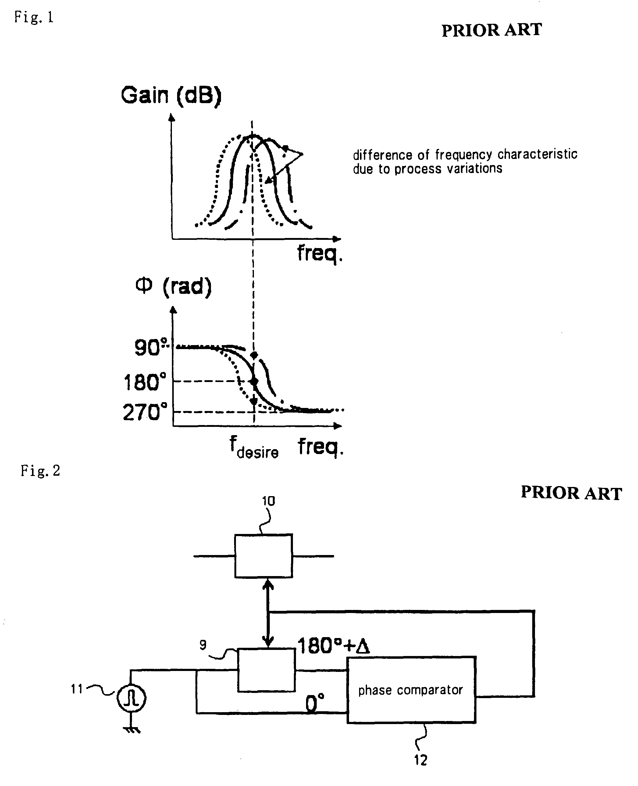
a filter circuit and automatic adjustment technology, applied in the field of automatic adjustment circuits, can solve the problems of increasing chip area and power consumption, unable to achieve full symmetry by simple background configuration, and reducing so as to minimize parasitic phase delay and increase the accuracy of phase comparison. , the effect of high accuracy

Active Publication Date: 2011-04-12
NEC CORP
View PDF18 Cites 1 Cited by
  • Summary
  • Abstract
  • Description
  • Claims
  • Application Information

AI Technical Summary

Benefits of technology

The task to be achieved by the present invention is to solve the above problems of the background art. It is an object of the present invention to provide an automatic adjustment circuit and a filter circuit which occupy a small chip area, has a low power consumption level, and is highly accurate and capable of high-speed operation.
With the above arrangement, phase offset errors produced at the instant of the changeover between high and low levels of a plurality of input signals cancel out each other, increasing the accuracy for phase comparison.
The integrating circuit allows paths for outputting the respective input signals to be designed with high symmetry, for thereby minimizing a parasitic phase delay caused by circuit asymmetry.
For the above reasons, according to the present invention, the automatic adjustment circuit is capable of adjusting frequency characteristics with high accuracy and also of high-speed operation.

Problems solved by technology

However, no full symmetry can be achieved by simple configurations of the background art (a double-balanced-mixer phase comparator, a phase comparator employing logic circuits, etc.).
If the phase comparator is larger in scale, then the parasitic phase delay increases, making it difficult for the phase comparator to operate at a high speed, and inviting an increase in the chip area and the power consumption.
For the reasons described above, the automatic adjustment circuit according to the background art is problematic in that it is difficult to increase the accuracy with which to adjust the frequency characteristics of the filter circuit.Patent document 1: JP-A No. 05-299971Patent document 2: JP-A No. 2003-347901

Method used


Image

  • Automatic adjustment circuit, and filter circuit
  • Automatic adjustment circuit, and filter circuit
  • Automatic adjustment circuit, and filter circuit

Examples


1st exemplary embodiment

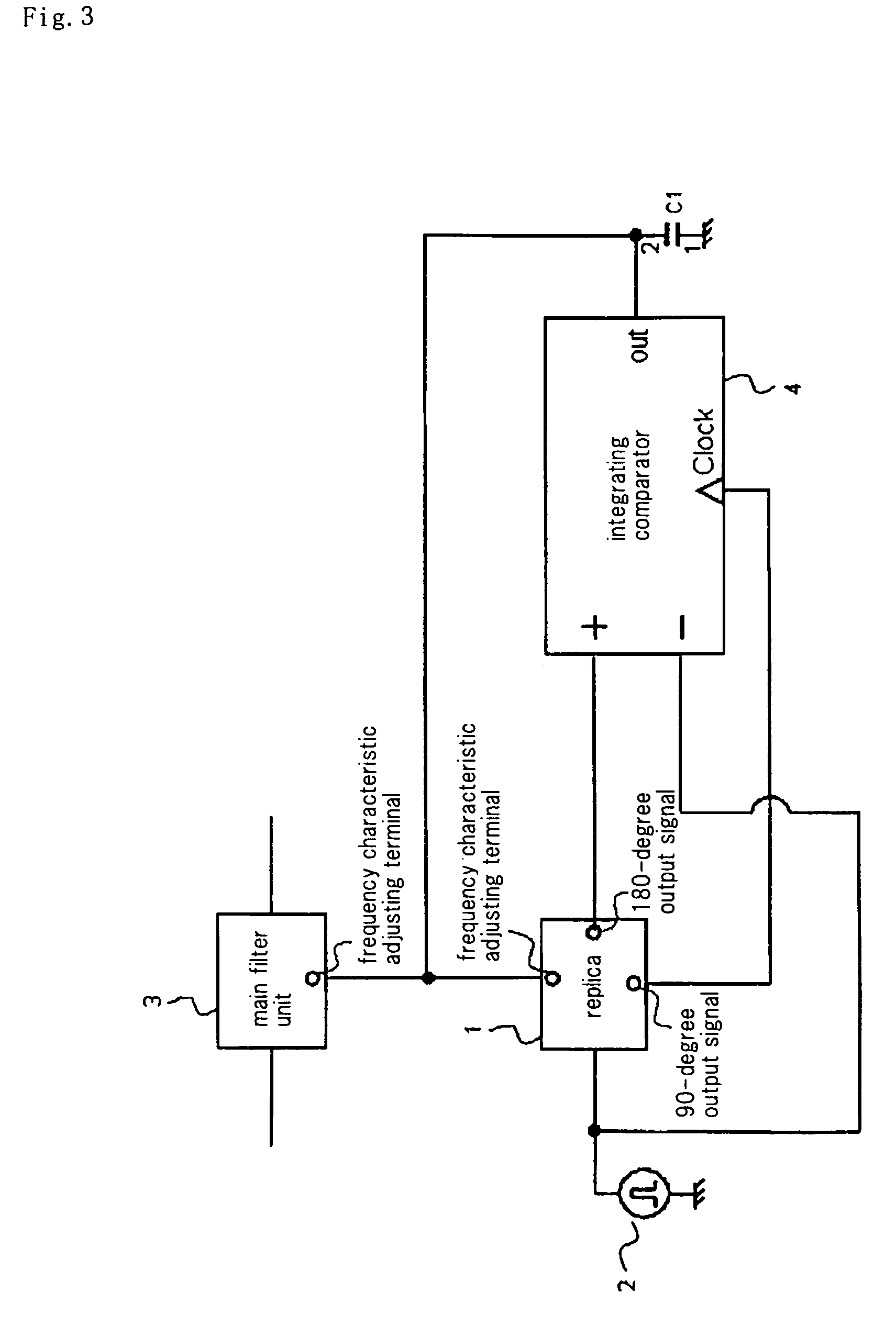
FIG. 3 is a diagram of an automatic adjustment circuit according to a first exemplary embodiment of the present invention. The automatic adjustment circuit is incorporated in a filter circuit.

In FIG. 3, 3 denotes a main filter unit and 1 a replica made up of a portion of a circuit block of main filter unit 3. Main filter unit 3 and replica 1 have respective frequency characteristic adjusting terminals. As a voltage applied to the frequency characteristic adjusting terminals goes higher, the frequency is adjusted to be higher. The frequency characteristic adjusting terminals of replica 1 and main filter unit 3 are connected to each other, and replica 1 and main filter unit 3 have respective frequency characteristics simultaneously adjusted to an optimum state. Replica 1 outputs a 180-degree output signal and a 90-degree output signal that are delayed in phase by 180 degrees and 90 degrees, respectively, from reference signal 2 input to replica 1. Integrating comparator 4 has a positi...

embodiment 1

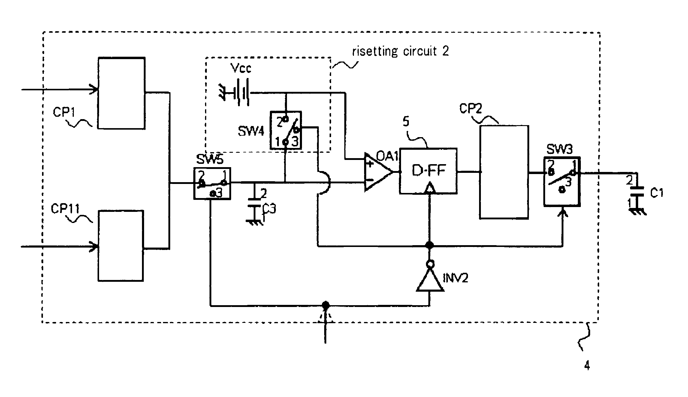
FIG. 9 shows an embodiment representing specific details of the first exemplary embodiment.

As with FIG. 3, the present embodiment comprises replica 1, reference signal 2, main filter unit 3, integrating comparator 4, and capacitor C1. These circuit components are connected in the same manner as with FIG. 3. Specific circuits of the respective blocks will be described below.

Main filter unit 3 is a gm-C filter comprising gm amplifiers and capacitors. Replica 1 is a second-order biquad filter comprising gm amplifiers gm1, gm2, gm3, gm4 and capacitors CG1, CG2 which are designed according to the same circuit topology as with main filter unit 3. Replica 1 has an input terminal connected therein to the input terminal of gm1, and an output terminal connected to the output terminal gm1, the input and output terminals of gm2, the input terminal of gm3, the output terminal of gm4, and terminal 2 of CG1 having terminal 1 grounded, in parallel relation to each other. The 90-degree output termin...


PUM


Abstract

An automatic adjustment circuit comprises a replica (1) constituted of either a circuit block of a portion of a filter body (3) or a combination of the circuit block, and fed with a reference signal (2) from the outside, for outputting signals having a phase delays of 90 degrees and 180 degrees with respect to the reference signal (2), and an integrating comparator (4) fed at its input terminal with an output signal, as having a phase delay of 180 degrees, of the replica (1) and the reference signal (2), and at its clock terminal with an output signal, as having a phase delay of 90 degrees, of the replica (1), and having an output terminal connected with a capacity (C1) and a frequency characteristic adjusting terminal of the replica (1). The automatic adjusting circuit is characterized in that the integrating action of the integrating comparator (4) is performed across the two high / low states of the input signal.

Description

TECHNICAL FIELDThe present invention relates to an automatic adjustment circuit for automatically adjusting frequency characteristics to target characteristics, and more particularly to an automatic adjustment circuit which is highly accurate and capable of high-speed operation.BACKGROUND ARTWith the development of the process technology in recent years, it has become possible to fabricate a high-functionality device, typified by a wireless device, made up of a variety of interconnected circuit blocks, as a one-chip IC (Integrated Circuit).A filter circuit, which is a circuit block of a radio device, serves to remove signals in unwanted frequency bands. Therefore, the filter circuit is required to have frequency characteristics that are higher in accuracy than the other circuit blocks of the radio device. Usually, the filter circuit incorporates an automatic adjustment circuit for adjusting the difference between designed values and actual frequency characteristics due to fabricatio...

Claims


Application Information

Patent Timeline
Patent Type & Authority Patents(United States)
IPC IPC(8): H03B19/00
CPCH03H11/1291H03H11/04
Inventor HORI, SHINICHI
Owner NEC CORP
Why Eureka
Try Eureka