

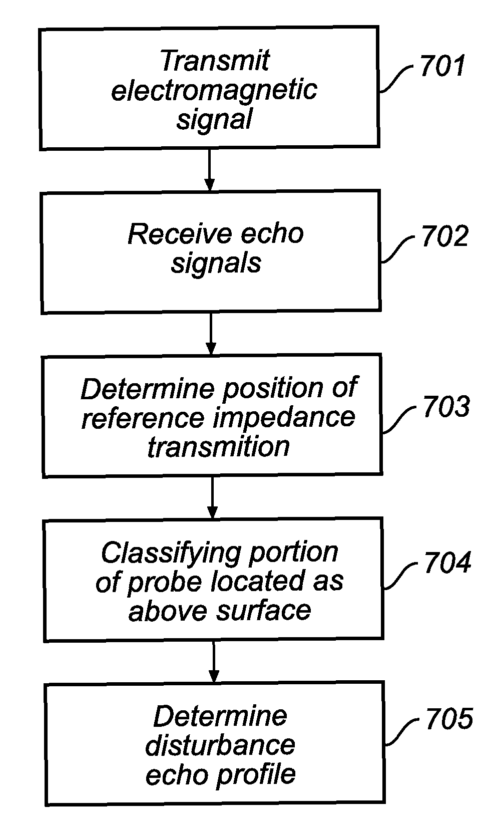
Method of determining a disturbance echo profile for a radar level gauge system
a radar level gauge and echo profile technology, applied in the direction of engine lubrication, liquid/fluent solid measurement, reradiation, etc., can solve the problems of system attempts to determine the filling level, small impedance transition, and relatively weak echo signal, and achieve reliable filling level determination
- Summary
- Abstract
- Description
- Claims
- Application Information
AI Technical Summary
Benefits of technology
Problems solved by technology
Method used
Image

Examples
Embodiment Construction
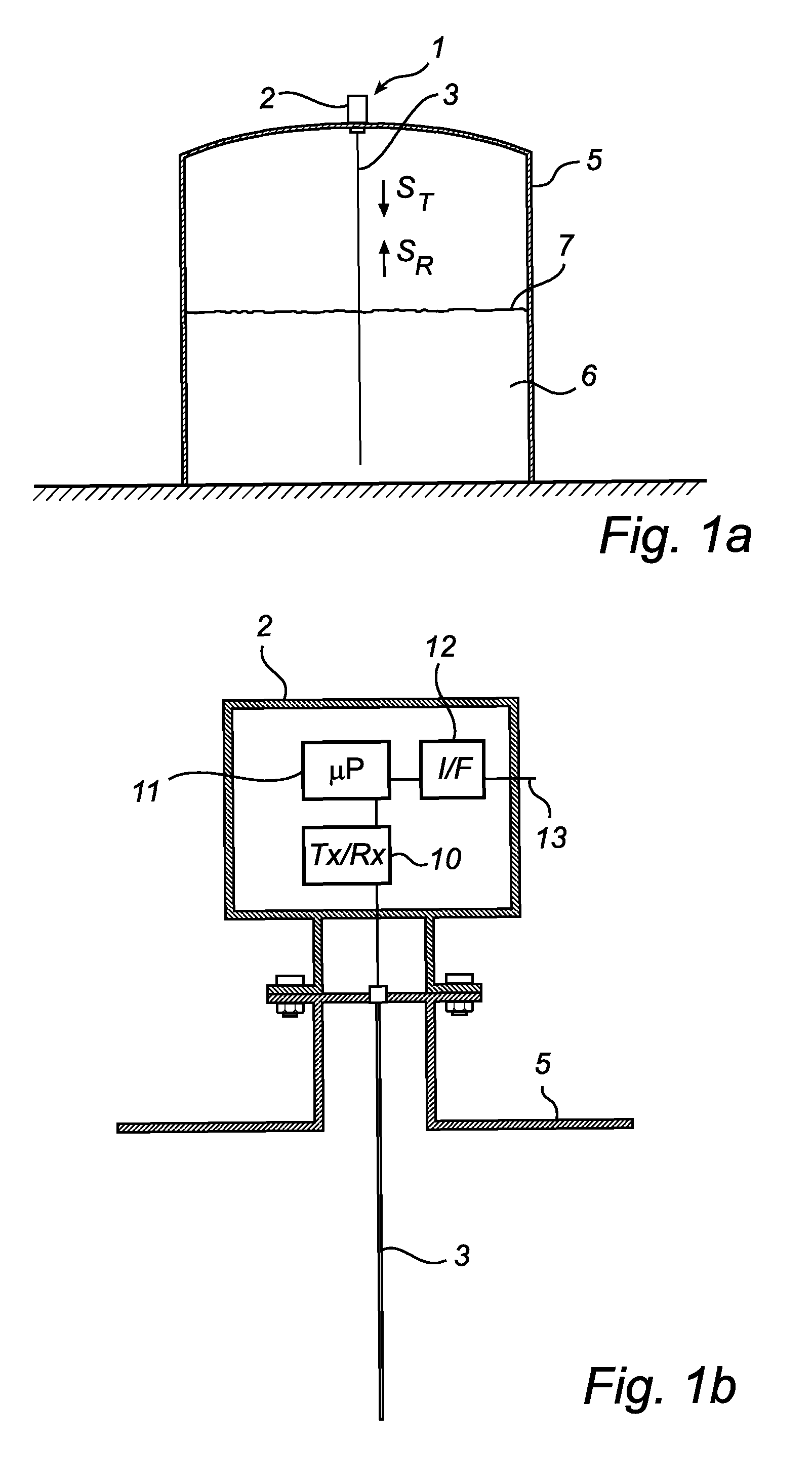
[0064]In the present detailed description, various embodiments of the radar level gauge system according to the present invention are mainly discussed with reference to a pulsed guided wave radar (GWR) level gauge system utilizing a single line probe. It should be noted that this by no means limits the scope of the present invention, which is equally applicable to GWR-systems being equipped with various other kinds of probes, such as two-lead probes, coaxial probes, etc.
[0065]Moreover, the present invention is also applicable to non-contact type radar level gauge systems, in which an electromagnetic signal is propagated towards the product contained in the tank using a radiating antenna, such as a cone antenna or a patch antenna.
[0066]Furthermore, reference is mainly made to filling level determination by means of measuring the time between transmitted and reflected pulses. As is, however, evident to the person skilled in the relevant art, the teachings of the present invention are ...
PUM
 Abstract
Description
Claims
Application Information