
Third rail power insulating system

a technology of power insulation and third rail, which is applied in the direction of power rails, connection contact material, transportation and packaging, etc., can solve the problem of system being exposed to extreme ultraviolet light, and achieve the effect of retaining effectiveness and being easy to manufacture and maintain

Active Publication Date: 2011-04-19
MORALES MIGUEL ANGEL
View PDF4 Cites 37 Cited by
  • Summary
  • Abstract
  • Description
  • Claims
  • Application Information

AI Technical Summary

Benefits of technology

[0012]It is another object of this invention to provide such a system that is inexpensive to manufacture and maintain while retaining its effectiveness.

Problems solved by technology

Such a system is subject to extreme ultraviolet light exposures, thermal variations, and extreme wind load conditions.

Method used


Image

  • Third rail power insulating system
  • Third rail power insulating system
  • Third rail power insulating system

Examples


Embodiment Construction

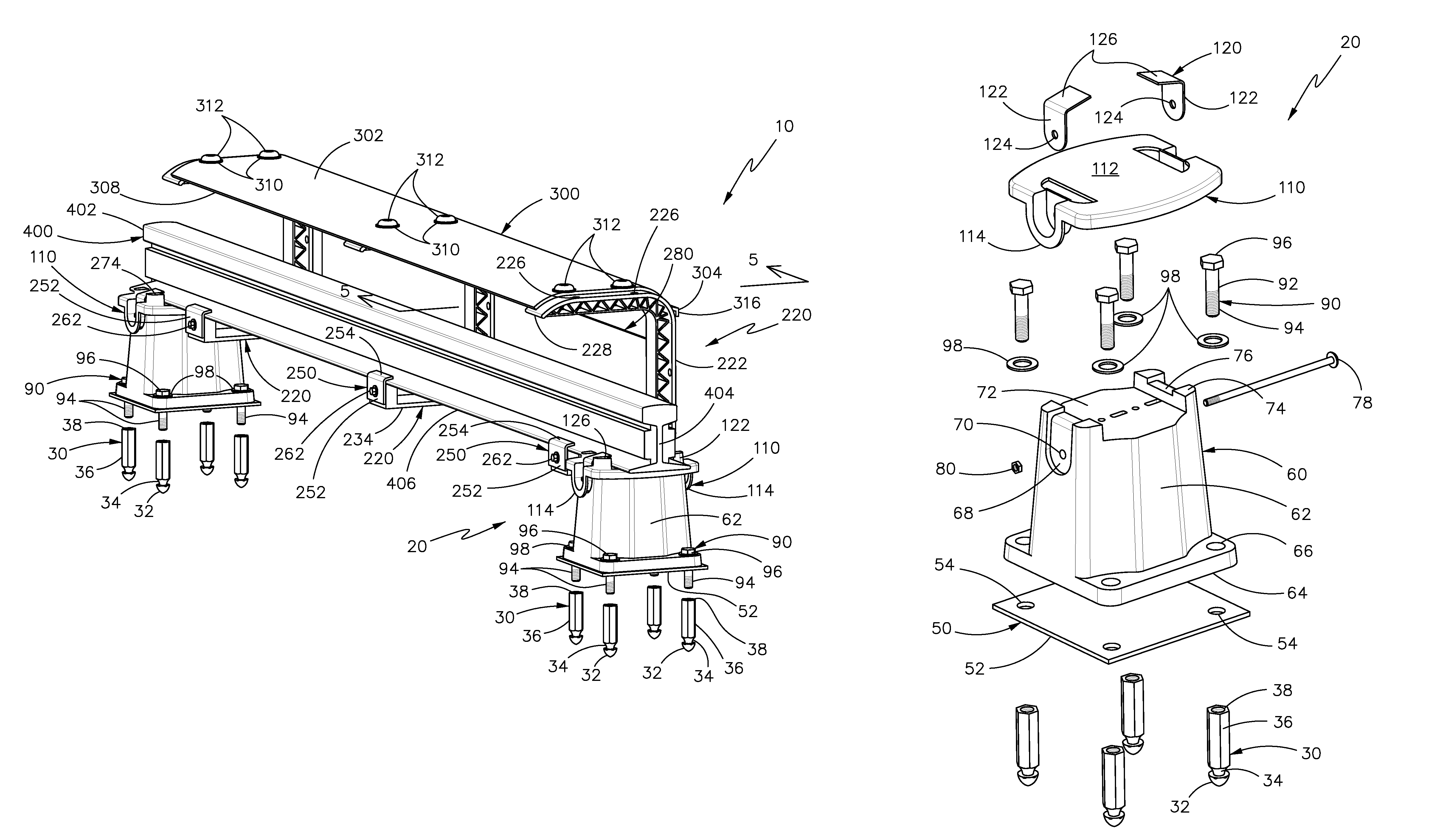
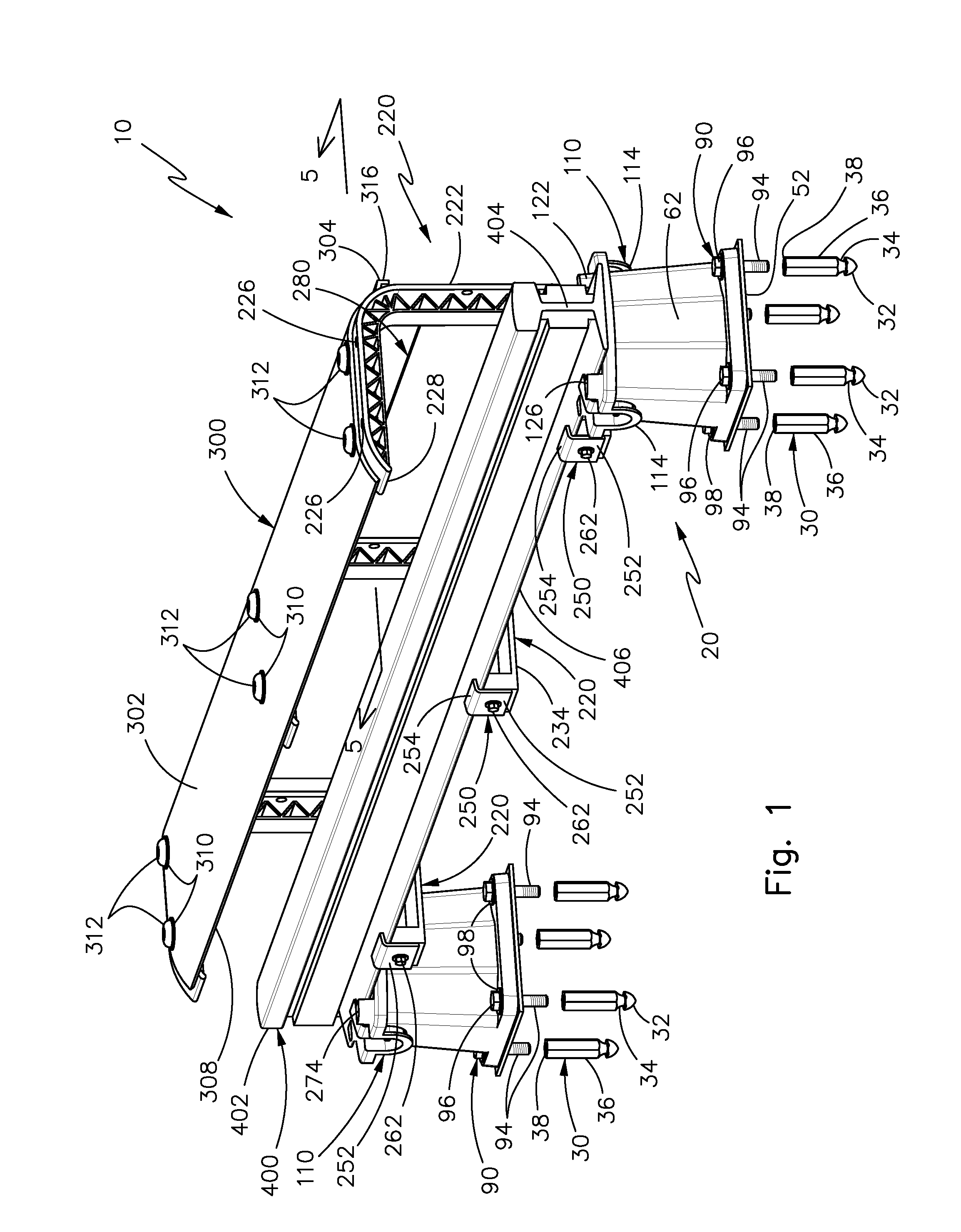
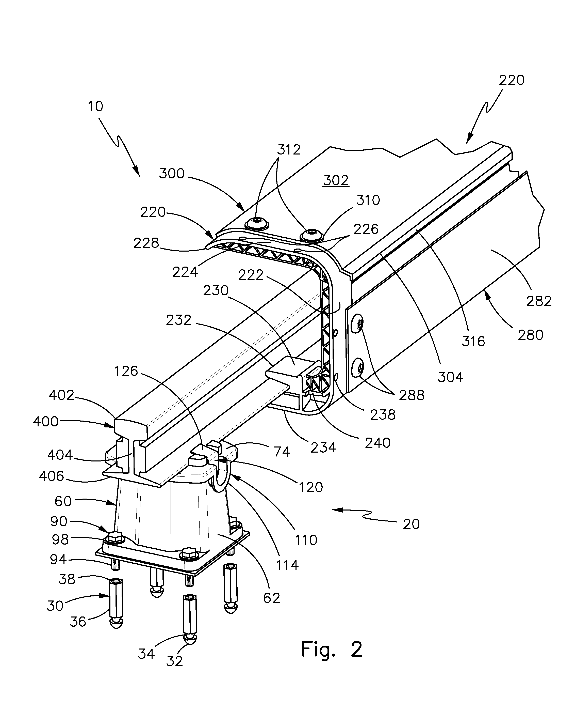
[0020]Referring now to the drawings, the present invention is generally referred to with numeral 10. It can be observed that it basically includes insulator assembly 20, and cover board assembly 200.

[0021]As seen in FIGS. 1 and 2, insulator assembly 20 and cover board assembly 200 are mounted onto contact rail assembly 400. Contact rail assembly 400 comprises head 402 extending from neck 404 and having base 406.

[0022]Although not illustrated, contact rail assembly 400 is part of a contact rail system, which supplies positive power source to transit vehicles. The contact rail system is an arrangement of components consisting of contact rail, splice bars and pin bolts, anchor assemblies, expansion joints, end approaches, dip rail sections, and fastening hardware. Contact rail assembly 400 is a trackside conductor consisting of steel rail with aluminum bars attached on webs that are used to transmit electrical energy from a power source to a transit vehicle via current-collector shoes....


PUM


Abstract

A third rail power insulating system, comprising an insulator assembly and a cover board assembly. The insulator assembly comprises pedestal supporting insulators that are mounted onto a contact rail assembly. The insulator assembly further comprises an insulator anchor bolt assembly, a base shim plate, a bolt assembly, a lubricating shim, and retaining clips. The cover board assembly is also mounted onto the contact rail assembly and it comprises a support bracket assembly, retaining clips, a side cover board, and a top cover board. The support bracket assembly has a general C-shape and comprises a lateral wall, a top wall, a base wall, and a protrusion. The side cover board comprises an elongated plate having at least one hole, and the top cover board comprises an elongated plate having sufficient curvature to contour the support bracket assembly.

Description

BACKGROUND OF THE INVENTION[0001]1. Field of the Invention[0002]The present invention relates to insulating systems, and more particularly, to third rail power insulating systems.[0003]2. Description of the Related Art[0004]Elevated rapid transit systems comprise a contact rail system that is typically installed on an at-grade track and on aerial guideway supporting trackwork. The height of the contact rail system on the aerial guideway is typically 40′ above surrounding ground, and at some locations can range up to 75′ above the surrounding ground.SUMMARY OF THE INVENTION[0005]The instant invention is a third rail power insulating system. In the preferred embodiment, a design of a contact rail system is based approximately on a nominal 10′ spacing of pedestal supporting insulators, with exceptions for the insulator spacing in dip sections or end approach sections. At those locations, a supplier provides spacing, which is compatible with these specification requirements and with the...

Claims


Application Information

Patent Timeline
IPC IPC(8): B60M1/00
CPCB60M1/307B60M1/04
Inventor MORALES, MIGUEL ANGEL
Owner MORALES MIGUEL ANGEL
Learn More