Synthetic sling whose component parts have opposing lays

a technology of synthetic slings and components, applied in the field of industrial slings, can solve the problems of synthetic slings being subjected to overload conditions, damage to synthetic slings, and failure of all loops, and achieve the effect of greater strength

Active Publication Date: 2011-04-19
SLINGMAX INC
View PDF12 Cites 16 Cited by
  • Summary
  • Abstract
  • Description
  • Claims
  • Application Information

AI Technical Summary

Benefits of technology

[0018]Applicant has found that twisting the loops of core yarns in a helical pattern results in a 12-15% increase in strength of the load-bearing core. In other words, with no other changes other than twisting the load-bearing core yarns, a sling achieves a significant increase in the weight of the load the sling can lift. Alternatively, a sling manufacturer that twists the core yarns can use 12-15% less core yarns to make a sling having the same load rating as a sling with substantially parallel or untwisted loops of core yarns.
[0023]Testing has shown that a load-bearing core made from core yarns twisted together offers greater strength than a load-bearing core made from yarns that are not twisted together. Although it is known to twist wire strands together to make wire rope, Applicant knows of no prior art synthetic slings manufacture that twist their core yarns. The subject method of twisting core yarns is a vast improvement over previous methods of twisting wire strands that involve specialized machinery. These special machines include using a spinning wheel with holes where the wire strands of the core material go through. The present invention avoids the requirement of specialized machinery and complicated methods with a novel method of twisting the core material. Previous to this invention, there was no way to twist the core material without the adoption of special machinery.

Problems solved by technology

Until recently, when an inspection of a synthetic sling uncovers damage to the load-bearing core, it was assumed that the sling was subjected to an overload condition.
However, it is now believed that a common cause of damage to a synthetic sling is a result of the manufacturing process.
As described previously, the lack of uniformity in length in the loops of core yarns that form the load-bearing core results in the shortest loops bearing the entire load, while the longest loops have virtually no load.
This process, if allowed to progress, will eventually lead to the failure of all loops and a complete failure of the load-bearing core.
The problem with twisting the core yarns in a helically-laid bundle is to invent a machine or a method that can perform this twisting in an efficient and cost-effective manner.

Method used


Image

  • Synthetic sling whose component parts have opposing lays
  • Synthetic sling whose component parts have opposing lays
  • Synthetic sling whose component parts have opposing lays

Examples


Embodiment Construction

[0036]In describing a preferred embodiment of the invention, specific terminology will be selected for the sake of clarity. However, the invention is not intended to be limited to the specific terms so selected, and it is to be understood that each specific term includes all technical equivalents that operate in a similar manner to accomplish a similar purpose.

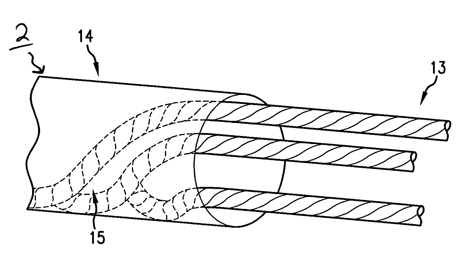
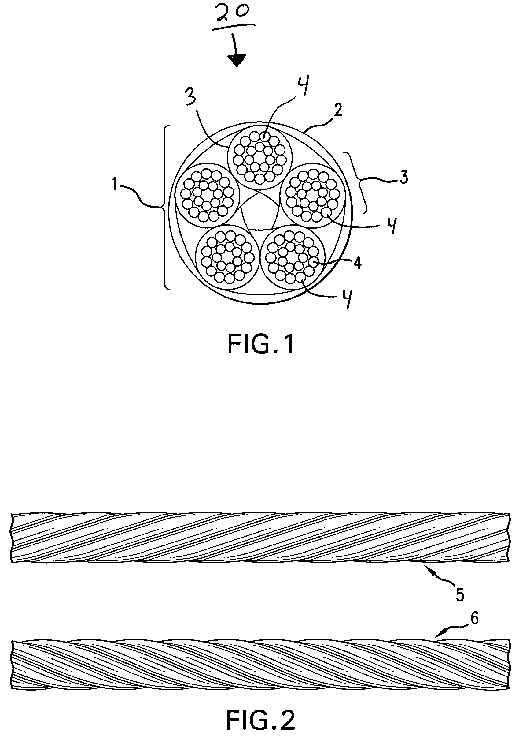
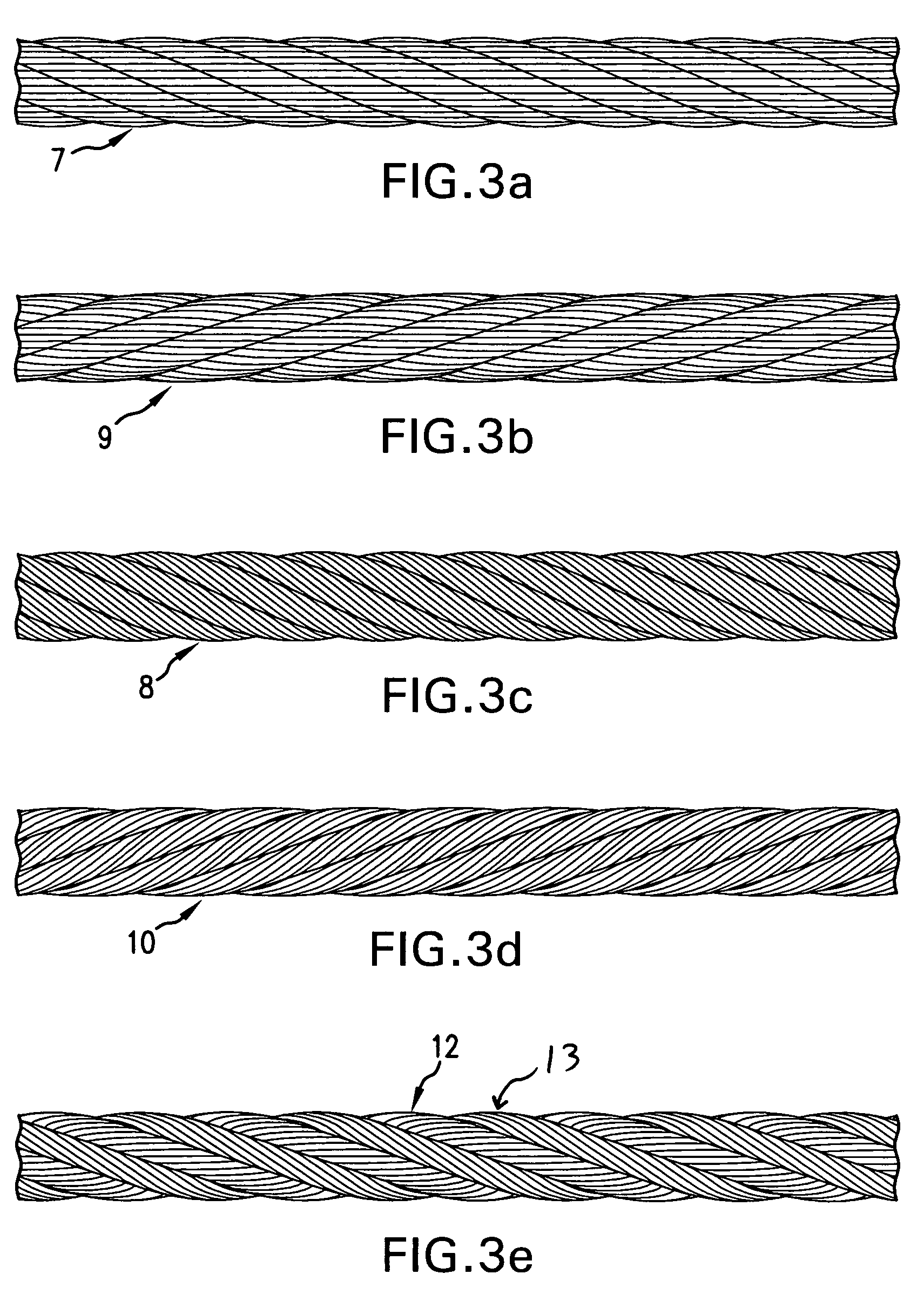
[0037]Synthetic slings have gained popularity over the last twenty years and are replacing metal slings in many circumstances. Synthetic slings are usually comprised of a lifting core made of a plurality of yarns or strands of synthetic fiber and an outer cover that protects the core. Each individual core yarn is, in turn, made from a plurality of threads. The cover is manufactured from a plurality of fibers.

[0038]The most popular design of synthetic slings is a roundsling in which the load-bearing core is formed from a plurality of core yarns formed in a continuous loop (in a substantially parallel configuration) resulting in...


PUM

PropertyMeasurementUnit
frictionaaaaaaaaaa
flexibilityaaaaaaaaaa
strengthaaaaaaaaaa

Abstract

A sling for industrial lifting made of a load-bearing core and a cover. The cover protects the plurality of yarns that make-up the core. Each core yarn is made of a number of core threads twisted together. The core yarns are twisted together where the twist is in the same direction as the individual core strands and a different direction than the twist of the cover. The present invention describes the method of twisting the core yarns together by inserting core yarns substantially parallel into a cover that has a twist opposite of each core strand. As the core strands are inserted into the cover, the twists of the individual core yarns interact with the twist of the cove, resulting in the core yarns twisting together.

Description

CROSS-REFERENCE TO RELATED APPLICATION[0001]The present application is a continuation-in-part and claims the benefit under any applicable U.S. statute to U.S. application Ser. No. 11 / 981,110 filed Oct. 31, 2007, in the name of Dennis St. Germain, titled Apparatus for Making Slings.[0002]This application incorporates by reference U.S. application Ser. No. 11 / 981,110 as if fully set forth herein.FIELD OF THE INVENTION[0003]The present invention relates generally to industrial slings and, more particularly, to the relationship between the load-bearing core and protective covers for non-metal slings.BACKGROUND OF THE INVENTION[0004]Industrial slings used in rigging or to lift, load, tow and / or move heavy loads are well-known in the art. At one time, industrial slings were made exclusively of wire-rope or chains. During the past twenty-five years, these industrial slings made of metal have seen improvements in flexibility and strength. However, despite the improvements, metal wire-rope s...

Claims


Application Information

Patent Timeline
Patent Type & Authority Patents(United States)
IPC IPC(8): B66C1/12
CPCB66C1/12D07B7/165D07B2401/2055D07B2205/205D07B2205/2039D07B2205/201D07B2201/2024D07B2201/1048D07B2201/1052D07B2201/1056D07B2201/2023D07B2801/12
Inventor ST. GERMAIN, GEORGE FREDERICK DENNIS
Owner SLINGMAX INC
Why Eureka
Try Eureka