Support platform of non-contact transfer apparatus

a technology of support platform and transfer apparatus, which is applied in the direction of electrical apparatus, basic electric elements, loading/unloading, etc., can solve the problems of increasing process costs, object scratching, uneven pressure distribution on the active surface of the support platform, etc., to achieve stably transfer an object, reduce air consumption, and high air pressure

Active Publication Date: 2011-04-19
LG DISPLAY CO LTD +2
View PDF13 Cites 4 Cited by
  • Summary
  • Abstract
  • Description
  • Claims
  • Application Information

AI Technical Summary

Benefits of technology

[0018]An advantage of the present invention is to provide a support platform of a non-contact transfer apparatus that can dramatically reduce the consumption of air.
[0019]Another advantage of the present invention is to provide a support platform of a non-contact transfer apparatus that can stably transfer an object.
[0020]Additional advantages and features of the invention will be set forth in part in the description which follows, and in part will be apparent from the description or may be learned by practice of the invention. These and other advantages of the invention may be realized and attained by the structure particularly pointed out in the written description and claims hereof as well as the appended drawings.
[0021]To achieve these and other advantages and in accordance with the purpose of the invention, as embodied and broadly described herein, there is provided a support platform of a non-contact transfer apparatus, the support platform being arranged horizontally and including: first and second members adding a lift force to a first force for lifting peripheral portions of a transferred object, wherein the first force is lower than a second force lifting a central portion of the transferred object.
[0022]In another aspect of the present invention, there is provided a support platform of a non-contact transfer apparatus, wherein the support platform is arranged horizontally and has a substantially rounded shape that protrudes downward such that a relatively high air pressure can be applied to peripheral portions of a transferred object and a relatively low air pressure can be applied to a central portion of the transferred object.
[0023]In another aspect of the present invention, there is provided a support platform of a non-contact transfer apparatus, the support platform being erected on a horizontal surface at a predetermined angle with respect to the horizontal surface and including: a member adding a lift force to a first force for lifting an upper peripheral portion of a transferred object, wherein the first force is lower than a second force for lifting a central portion of the transferred object.

Problems solved by technology

In the case of the contact transfer apparatus, since the object is transferred in a state where it contacts the support platform, the object may be scratched due to the friction between the object and the support platform or broken.
In the non-contact transfer apparatus of the related art, since each air intake hole 101 through which the air is introduced has a predetermined diameter, a large amount of air is consumed to form the air cushion 104 on the active surface 107, thereby increasing the process costs.
That is, the pressure distribution is not uniform throughout the active surface of the support platform.
Therefore, the object lifted from the platform may jolt or collide with a periphery of the object.
This causes damage to the object.

Method used


Image

  • Support platform of non-contact transfer apparatus
  • Support platform of non-contact transfer apparatus
  • Support platform of non-contact transfer apparatus

Examples


first embodiment

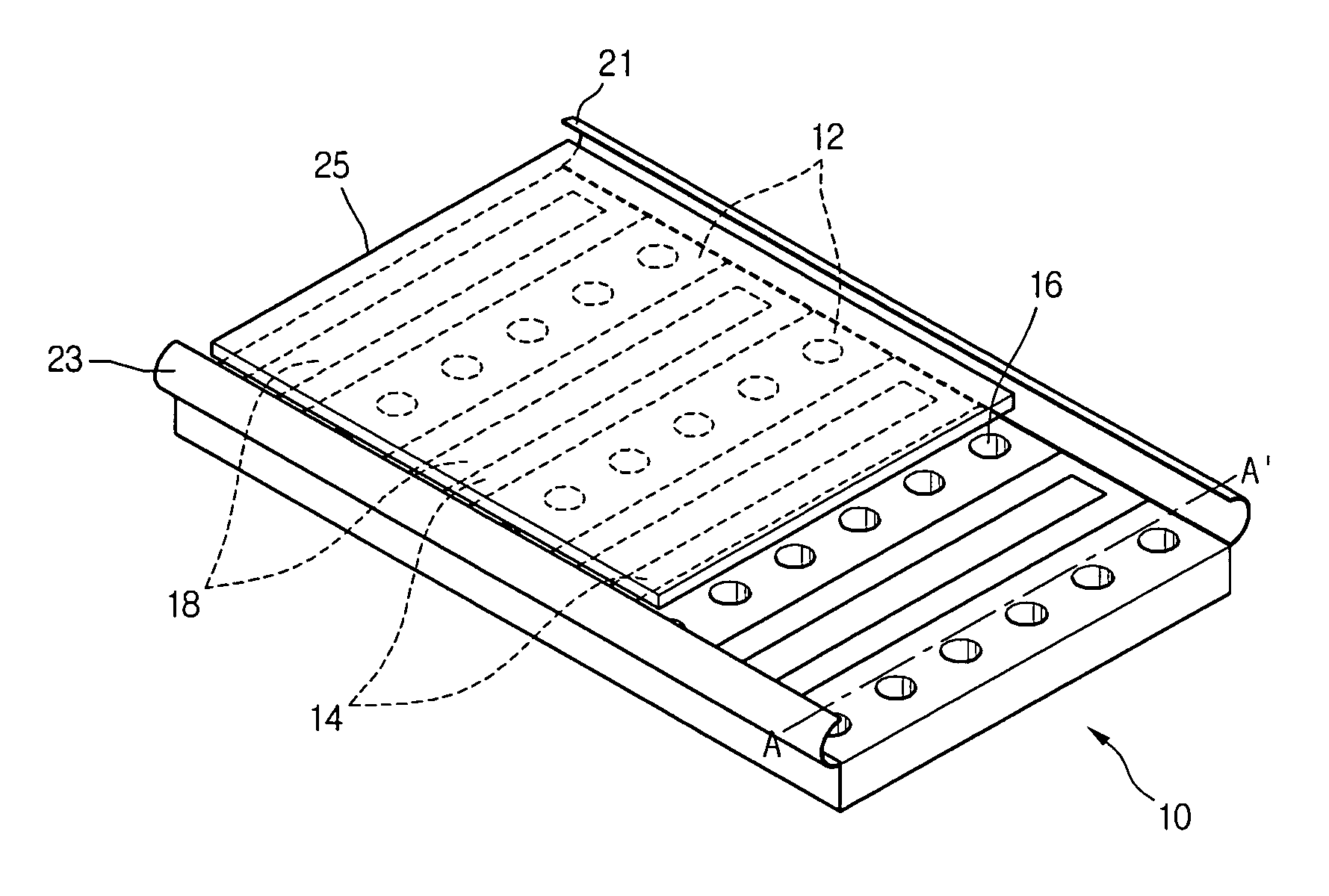
[0040]FIG. 3 is a schematic perspective view of a support platform of a non-contact transfer apparatus according to the present invention and FIG. 4 is a sectional view taken along line A-A′ of FIG. 3.

[0041]Referring to FIGS. 3 and 4, a support platform of this embodiment includes a plurality of air pads 12 and a plurality of dummy pads 14. The air pads 12 and the dummy pads 14 are alternately connected to each other and formed in a rectangular shape. The air and dummy pads 12 and 14 may be identical in a size to each other. In this embodiment, the air pads 12 may be connected to the dummy pads 14 by, for example screws or adhesive. The air and dummy pads 12 and 14 are arrayed in an alternating pattern with each other and form a guide pad 10.

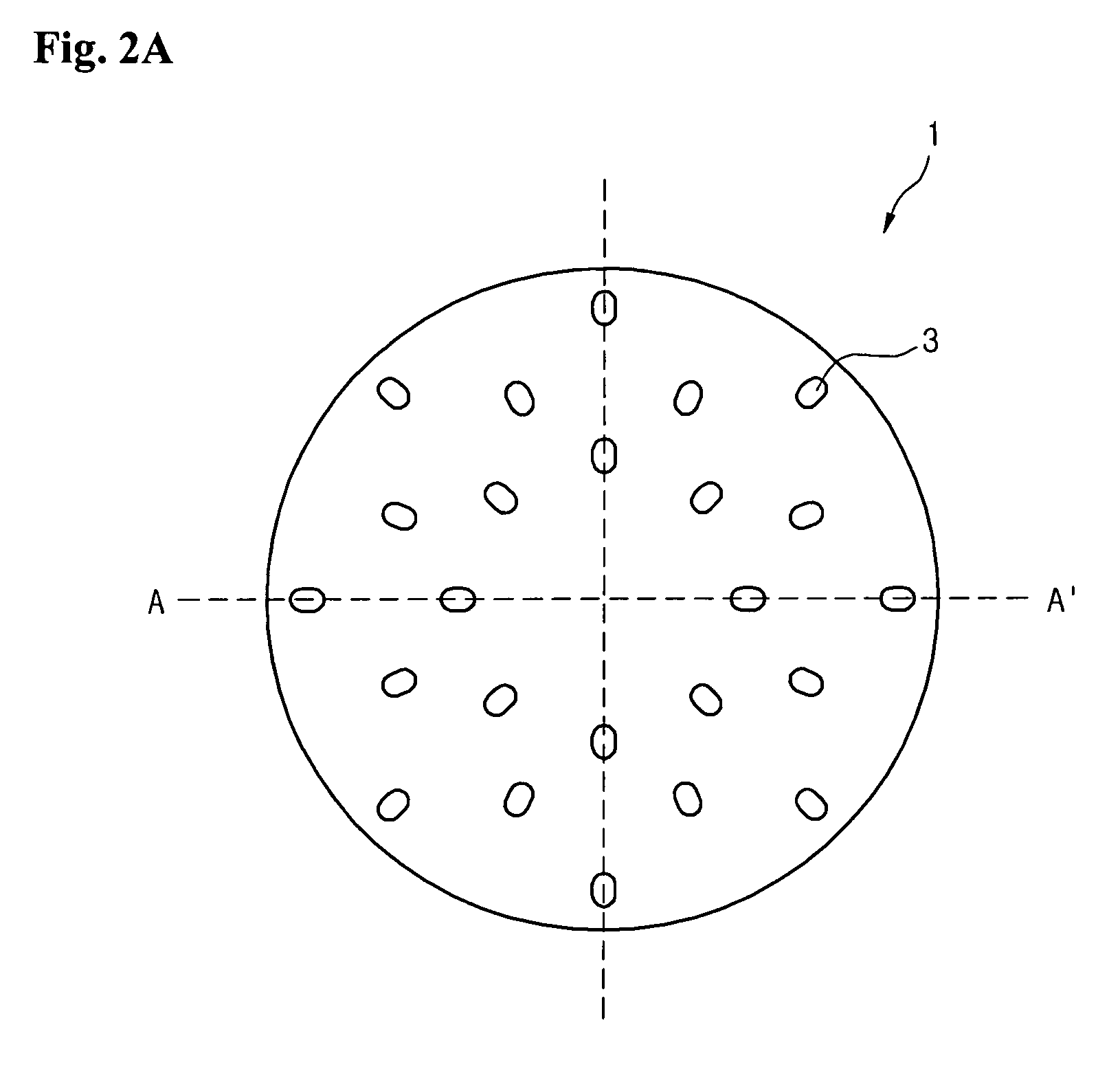
[0042]A plurality of air intake hole portions 16 are formed in a line on each air pad 12. A plurality of sub-holes (3 of FIG. 2A) are formed through each air intake hole portion 16 and arranged in a substantially radial direction. Since the sub-...

second embodiment

[0047]FIG. 5 is a schematic perspective view of a support platform of a non-contact transfer apparatus according to the present invention and FIG. 6 is a sectional view taken along line B-B′ of FIG. 5.

[0048]Referring to FIGS. 5 and 6, a support platform of this embodiment includes a plurality of air pads 32 and a plurality of dummy pads 34. The air pads 32 and the dummy pads 34 are alternately connected to each other and formed in a substantially rectangular shape. The air and dummy pads 32 and 34 may be identical in size to each other. In this embodiment, the air pads 32 may be connected to the dummy pads 34 by, for example, screws or adhesive. The air and dummy pads 32 and 34 respectively, are arranged in an alternating pattern with each other and form a guide pad 30.

[0049]A plurality of air intake hole portions 36 are formed in a line on each air pad 32 in a line. A plurality of sub-holes (3 of FIG. 2A) are formed through each air intake hole portion 36 and arranged in a substant...

third embodiment

[0054]FIG. 7 is a schematic view of a transfer apparatus having a support platform according to the present invention.

[0055]Referring to FIG. 7, a support platform 40 is installed at a predetermined inclination angle. The support platform 40 may be one of the first and second embodiments.

[0056]A transfer apparatus transfers an object 42 in a horizontal direction or in a vertical direction as shown in FIG. 7. When the support platform 40 is not operated, that is, when no air cushion is formed on the support platform 40, the object 42 leans on an upper portion of the support platform 40. However, when the support platform 40 is operated, the object 42 is pushed by the air cushion such that the object 42 can be transferred in a state where the object 42 is spaced apart from the support platform 40 by a predetermined interval.

[0057]A bottom of the object 42 seats on rollers. Therefore, the object 42 can be transferred in an advancing direction as the rollers 44 rotate. That is, when the...


PUM


Abstract

Provided is a support platform of a non-contact transfer apparatus. The support platform is arranged horizontally and includes first and second members adding a lift force to a first force for lifting peripheral portions of a transferred object, wherein the first force is lower than a second force lifting a central portion of the transferred object.

Description

CROSS-REFERENCE TO RELATED PATENT APPLICATION[0001]This application claims the benefit of Korean Patent Application No. 10-2005-0052914, filed on Jun. 20, 2005, which is incorporated by reference for all purposes as if fully set forth herein.BACKGROUND OF THE INVENTION[0002]1. Field of the Invention[0003]The present invention relates to a support platform of a non-contact transfer apparatus, and more particularly, to a support platform that can transfer objects under a non-contact state.[0004]2. Description of the Related Art[0005]Generally, in order to manufacture a semiconductor integrated circuit or a display panel, an object (for example, a substrate) undergoes a plurality of processes.[0006]In order to transfer the object from one process to another process, a transfer apparatus is used. A transfer apparatus that can efficiently transfer the object has been researched.[0007]Transfer apparatuses are classified into contact transfer apparatuses that can transfer the object in a s...

Claims


Application Information

Patent Timeline
Patent Type & Authority Patents(United States)
IPC IPC(8): B65G53/00
CPCH01L21/67784H01L21/68B65G47/91B65G49/06
Inventor KIM, SUNG EUNJEON, HYUN JOOYOO, HWAN KYUOH, JI YOUNGKWON, TAE KYUN
Owner LG DISPLAY CO LTD
Why Eureka
Try Eureka