Gripper, in particular a Bernoulli gripper

a technology of grippers and grippers, applied in the field of grippers, can solve problems such as source of danger, and achieve the effects of reducing air consumption, reducing waste, and accelerating lateral movemen

Inactive Publication Date: 2012-05-08
JONAS & REDMANN AUTOMATIONSTECHNIK GMBH
View PDF9 Cites 4 Cited by
  • Summary
  • Abstract
  • Description
  • Claims
  • Application Information

AI Technical Summary

Benefits of technology

[0009]The gripper according to the invention ensures that in each case the wafer to be attached by suction first establishes contact with the elastic bristles of the brush, and thus, in a manner of speaking, in the suction-induced approach to the gripping face of the gripper is gently damped in a mechanical manner before it comes to bear in a shock-resistant manner against the rubberized bearing surface of the bearing ring. In this arrangement it is immaterial whether or not the two-dimensional component is aligned parallel to the rubberized bearing surface; instead, in each case, the danger, during handling, of damaging the wafers that are susceptible to damage is reduced, and waste is thus considerably reduced. The rubberized bearing surface ensures the friction between the wafer to be gripped and the gripping surface of the gripper, which friction is necessary for rapid lateral movement.
[0010]Preferably, the damping device of the gripper, which damping device is circumferentially adapted to the gripper and protrudes circumferentially above the contour of the gripper, can also be an integrated sealing-like rubber ring from a suitable elastic material that is very soft, by means of which rubber ring the wafer in its suction-induced bearing against the rubberized bearing surface of the bearing ring, which bearing surface is integrated in the gripping face, is circumferentially hermetically sealed from the baffle plate through which the flow system passes. In this embodiment operation of the Bernoulli gripper needs to be switched over to vacuum operation immediately after suction-induced placement of the wafer against the rubberized bearing surface by switching a vacuum pump that is connected to an air connection of the flow system over to vacuum operation, while at the same time a second air connection of the flow system is switched off, which second air connection, for the purpose of generating the pressure differential for attaching the wafer by suction, was impinged upon by air. When the Bernoulli gripper attaches the wafer by suction the sealing-ring-like rubber ring contracts, thus forming a complete sealing circle with the wafer. Within the sealing circle a vacuum can form and consequently the wafer is pushed against the rubberized bearing surface by external atmospheric pressure, and is thus held in a slip-resistant manner. In this manner the air consumption can be reduced considerably while still achieving reliable holding of the wafer against the rubberized bearing surface of the bearing ring.

Problems solved by technology

However, the suction-induced non-decelerated impact, on the gripping face of the gripper, of the wafer being gripped has proven to be a source of danger as far as wafer damage is concerned.

Method used


Image

  • Gripper, in particular a Bernoulli gripper
  • Gripper, in particular a Bernoulli gripper
  • Gripper, in particular a Bernoulli gripper

Examples


Embodiment Construction

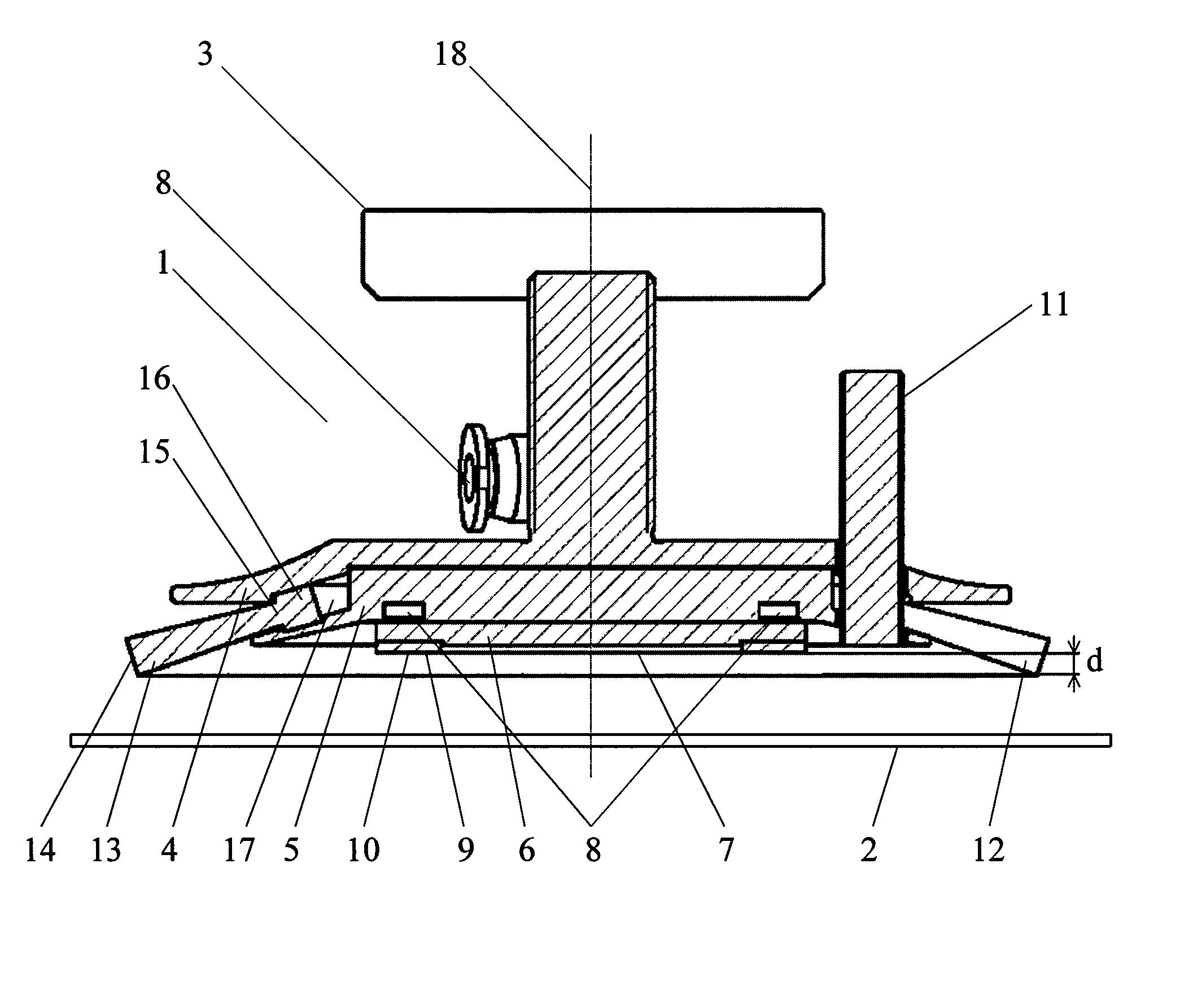
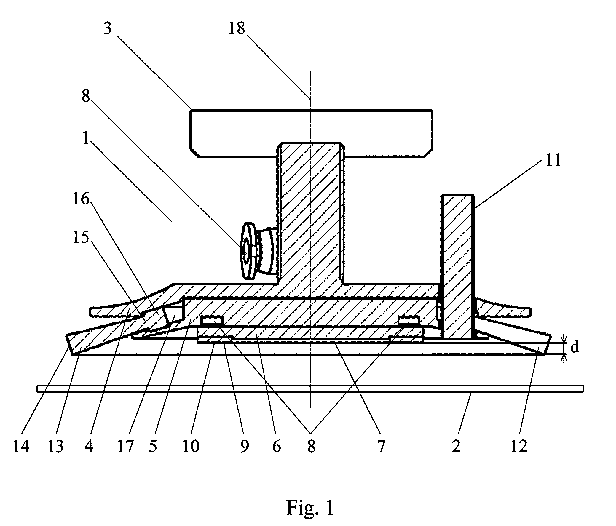
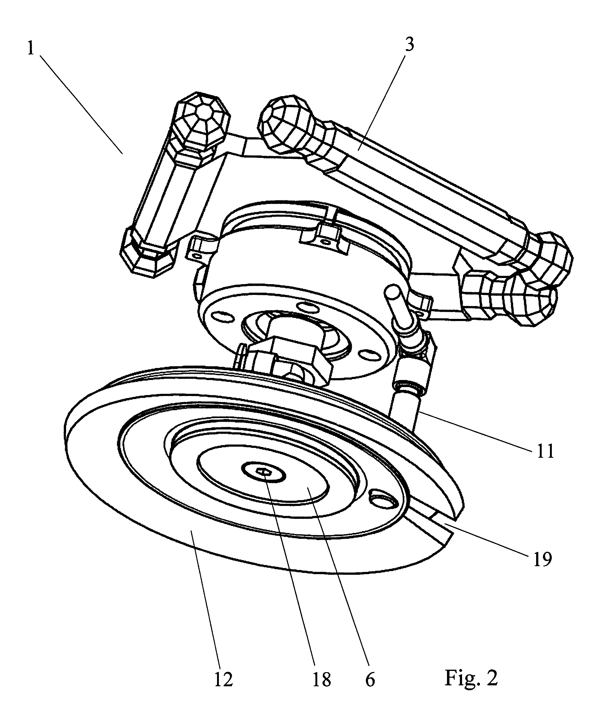
[0016]As shown in FIGS. 1 to 3, for non-contacting holding of two-dimensional components such as silicon-based wafers 2 the Bernoulli gripper 1 essentially comprises a clamping ring 4 that is connected to at least one controllable robot arm 3, a baffle plate 6 which is connected to the clamping ring 4 by way of a funnel-shaped component 5 and comprises a gripping face 7 in which a rubberized bearing surface 9 of a bearing ring 10 is integrated, a flow system 8 which flows through the funnel-shaped component 5 and the baffle plate 6, which flow system 8 communicates with the gripping face 7 of the gripper 1, a damping device 12, which is circumferentially adapted to the gripper 1, with the damping device 12 being in the form of a brush with elastic bristles and a capacitive sensor 11 to detect a wafer 2 held by the gripper 1.

[0017]If an excess pressure has been applied to the Bernoulli gripper 1, due to the pressure differential formed, a negative pressure is produced on the gripping...


PUM


Abstract

A gripper for holding two-dimensional components with a low degree of loading, has a clamping ring connected to a controllable robot arm with a baffle plate connected to the clamping ring by a funnel-shaped component and has a gripping face which communicates with a flow system which passes through the funnel-shaped component and the baffle plate. After an excess pressure has been applied to the gripper, a negative pressure is produced on the gripping face in order to attach by suction a wafer to be gripped. A rubberized bearing surface of a bearing ring integrated in the gripping face provides a slip-resistant movement of the wafer. A sensor detects the wafer hat is attached to the gripping face by suction. In order to permit an extremely shock-resistant attachment of the wafer to be gripped on the gripping face of the gripper, a damping device which is circumferentially adapted to the gripper has a contour as viewed in plan that protrudes circumferentially above the contour of the gripper and forms a damping resistance for the wafer.

Description

CROSS REFERENCE TO RELATED APPLICATIONS[0001]This is a 371 application on International Application PCT / DE2008 / 000789, filed May 5, 2008, which is incorporated herein by reference and which claims priority on German application 202007007721.1, filed May 31, 2007, which priority claim is repeated here.[0002]The invention relates to a gripper, in particular a Bernoulli gripper for holding in a non-contacting manner two-dimensional components such as silicon-based wafers having a clamping ring connected to a controllable robot arm, having a baffle plate which is connected to the clamping ring by means of a funnel-shaped component and has a gripping face which communicates with a flow system which passes through the funnel-shaped component and the baffle plate and by means of which, after an excess pressure has been applied to the Bernoulli gripper, a negative pressure is to be produced on the gripping face of the baffle plate in order to attach by suction the wafer to be gripped, havin...

Claims


Application Information

Patent Timeline
Patent Type & Authority Patents(United States)
IPC IPC(8): A47J45/00
CPCB25J15/0616H01L21/6838H01L21/67259Y10S294/907H01L21/687H01L21/683
Inventor JONAS, STEFANREDMANN, LUTZ
Owner JONAS & REDMANN AUTOMATIONSTECHNIK GMBH
Why Eureka
Try Eureka