Economizer Device For Linear Pneumatic Actuator

a linear pneumatic actuator and economizer technology, applied in fluid-pressure actuators, botany apparatus and processes, angiosperms/flowering plants, etc., can solve the problems of high energy cost, routine and extraordinary maintenance cost, and the cost of compressed air production is rather a significant percentage of total operating cost, so as to reduce the cost of compressed air consumption, the effect of unchanged performance and modest bulk and dimensions

Inactive Publication Date: 2014-07-10
LANDI ENZO
View PDF2 Cites 4 Cited by
  • Summary
  • Abstract
  • Description
  • Claims
  • Application Information

AI Technical Summary

Benefits of technology

[0008]Another object is to supply an economizer device that is installable on a linear pneumatic actuator and a method for controlling a linear pneumatic actuator that enables compressed air consumption to be lowered whilst maintaining unchanged performance (thrust and traction force on the piston, speed, acceleration) of the latter.
[0009]A further object is to make an economizer device that is compact, with modest bulk and dimensions and is easily installable on or integratable into a linear pneumatic actuator.
[0010]Still another object is to provide an economizer device having reliable and safe operation, that ensures optimum performance to the linear pneumatic actuator associated therewith.
[0011]Another further object is to make an economizer device that is installable on linear pneumatic actuators of a pneumatic plant and a method for controlling a linear pneumatic actuator, that enable the energy (e.g. electric energy) consumption to be reduced significantly that is required for supplying air to a compressing arrangement of the aforesaid plant and for also reducing wear to the aforesaid compression arrangement and the costs of routine and extraordinary maintenance thereof and of the costs of cleaning and filtering the air, eliminating condensate and cooling the air.

Problems solved by technology

In the analysis of running costs of an apparatus or of an operating machine and, more in general, of a manufacturing company provided with a plurality of operating machines and of pneumatic plants, the cost of producing compressed air is rather a significant percentage of total operating costs.
This cost comprises not only the energy cost (e.g. electric energy) required for supplying the compression arrangement, but also the cost of routine and extraordinary maintenance of the latter, the use of air cleaning and filtering systems, removal of condensate, air-cooling, etc.
Using lower operating pressure in a pneumatic plant would thus enable energy to be saved but would lower performance or even lead to a malfunction at the work points where pressure is higher.

Method used


Image

  • Economizer Device For Linear Pneumatic Actuator
  • Economizer Device For Linear Pneumatic Actuator
  • Economizer Device For Linear Pneumatic Actuator

Examples


Embodiment Construction

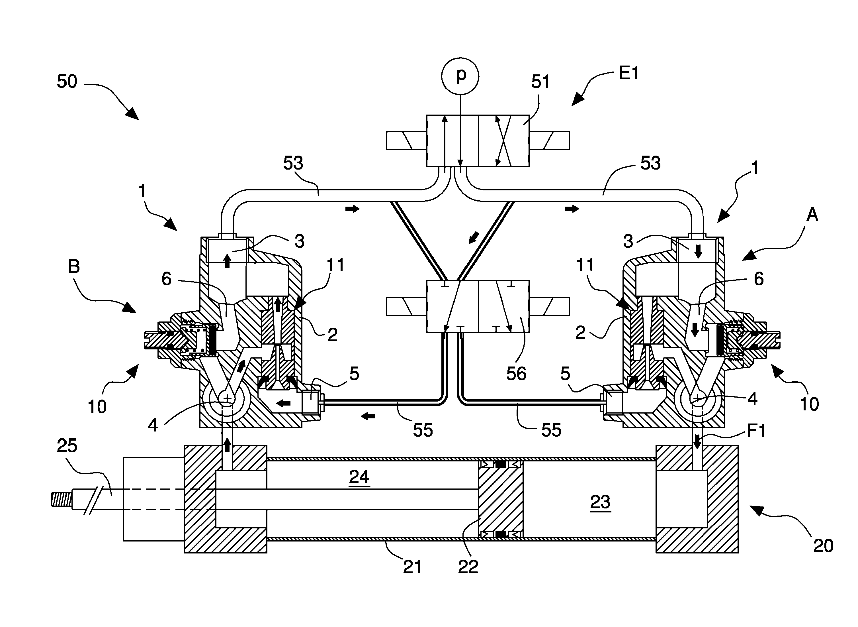
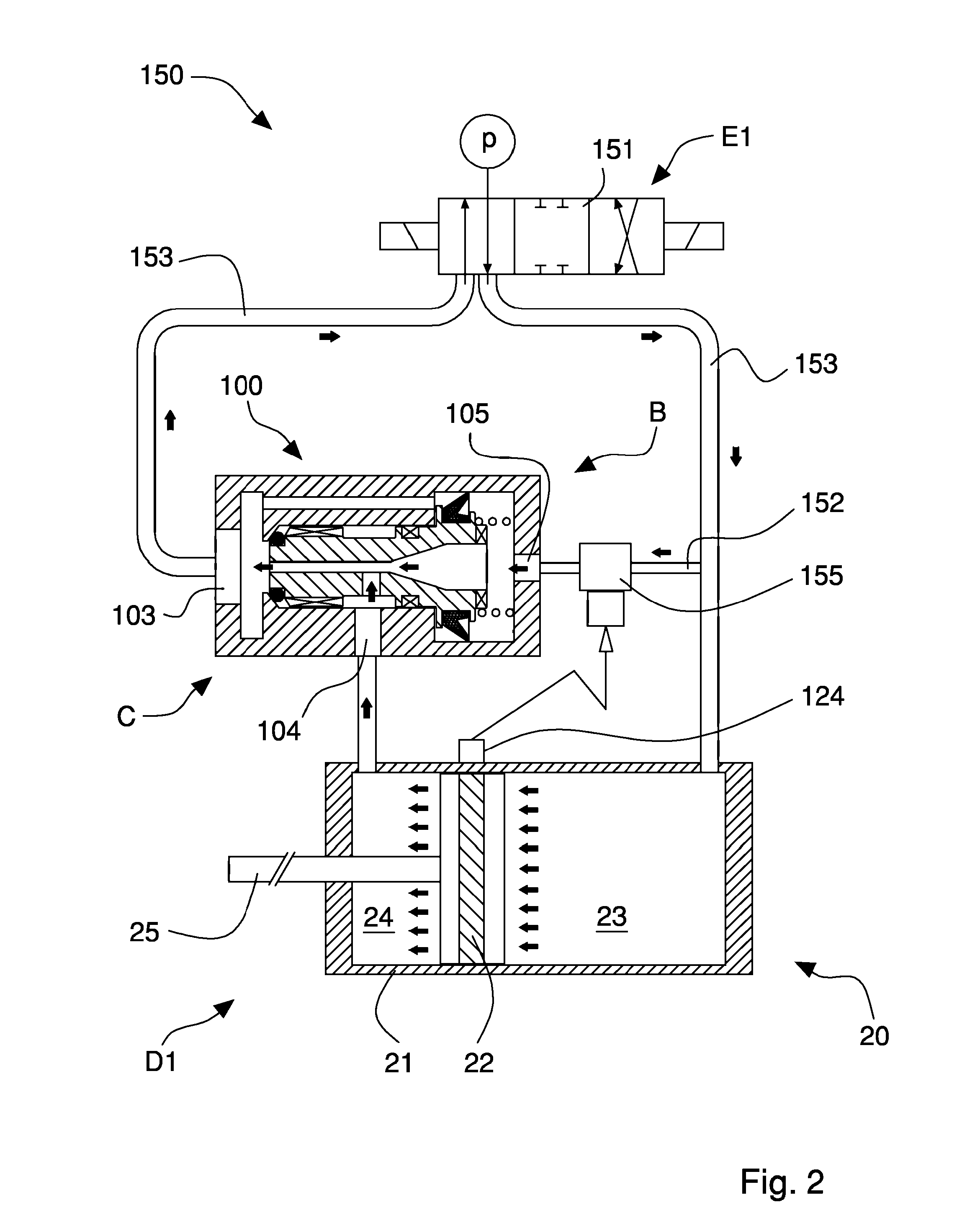
[0026]With reference to FIGS. 1 to 3, an economizer device 100 according to the invention is illustrated that is associated with a linear pneumatic actuator 20, in particular a pneumatic cylinder, comprising an external casing 21 (cylinder) and a piston 22 provided with a stem 25 and slidable inside said casing 21, defining in the latter a first chamber 23 and a second chamber 24.

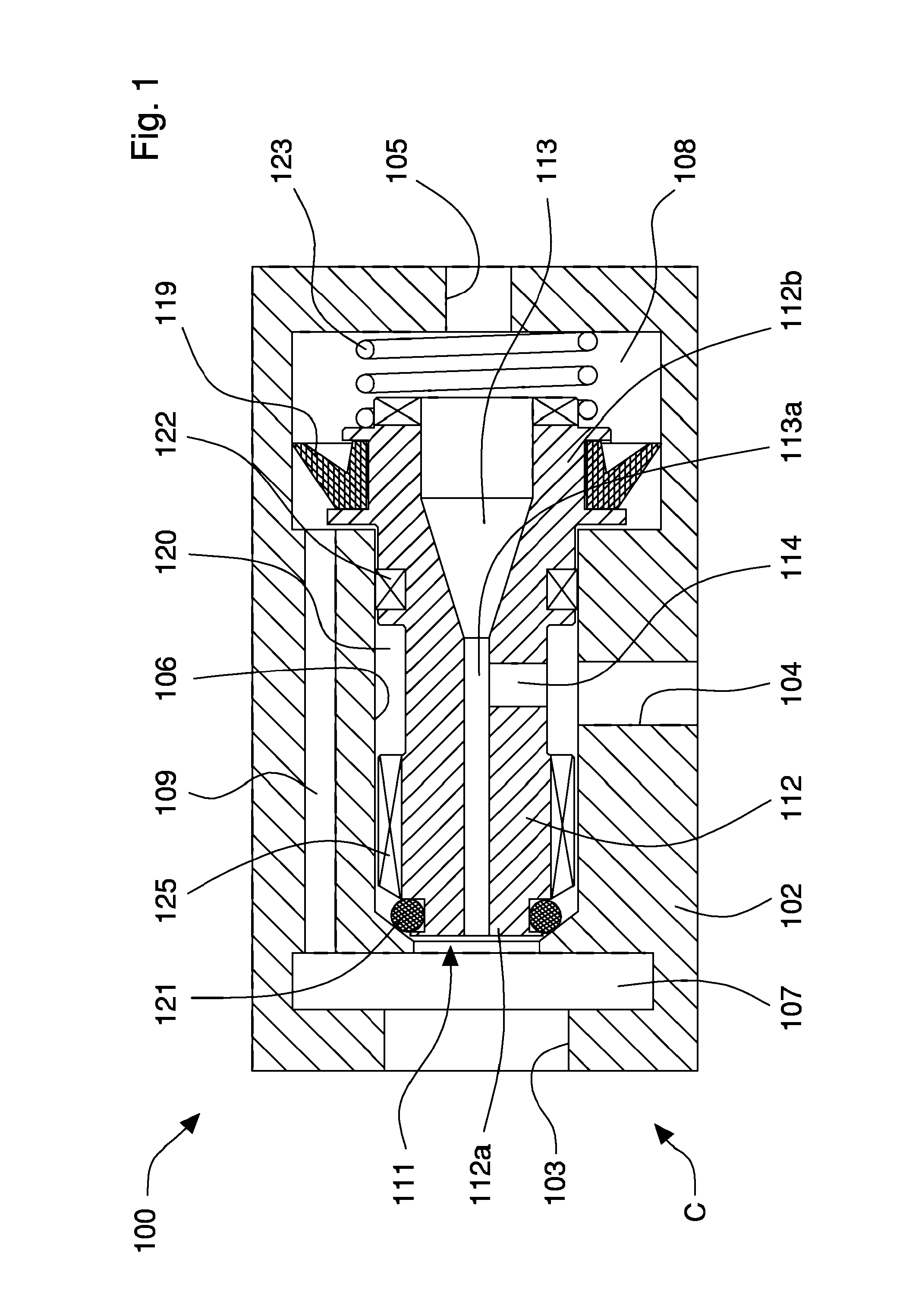
[0027]The economizer device 100 comprises a body 102 of substantially cylindrical or prismatic shape, provided with a first opening 103 that can be selectively connected to a source of pressurized air or to an environment at atmospheric pressure (exhausted), a second opening 104 connectable to one of the chambers 23, 24 of the pneumatic cylinder 20, for example to the second chamber 24, and a third opening 105 selectively connectable to a source of pressurized air.

[0028]The openings 103, 104, 105 are connected together by a first conduit 106 in which a Venturi vacuum generator, or Venturi vacuum pump 111 is...


PUM


Abstract

An economizer device associable with a linear pneumatic actuator includes a body having openings and a Venturi vacuum generator slidably housed in a first conduit. The device operates between a first operating configuration, where a first opening is supplied with air at an operating pressure and the vacuum generator moves in the first conduit to permit primary flow of air and to reduce outlet pressure thereof from a second opening so as to supply the chamber of the actuator with air at a reduced pressure lower than the operating pressure, and a second operating configuration, where the first opening is connected to the environment at atmospheric pressure and a third opening is supplied with pressurized air with which it supplies the vacuum generator, which creates a vacuum in the second opening in such a manner as to suck air from and create a vacuum in the chamber.

Description

FIELD OF THE INVENTION[0001]The invention relates to pneumatic plants and circuits for apparatuses and operating machines and, in particular, it refers to an economizer device that is installable on linear pneumatic actuators to reduce the consumption of compressed air thereof whilst maintaining performance unvaried. The invention further relates to a movement apparatus comprising a linear pneumatic actuator provided with an economizer device and a method for driving a linear pneumatic actuator.BACKGROUND OF THE INVENTION[0002]Known linear pneumatic actuators are typically pneumatic cylinders that comprise a casing or hollow external container (cylinder) inside which a piston with stem slides that divides the interior of the cylinder into two chambers. In single-acting cylinders only one of the chambers is supplied with compressed air so as to exert a thrust force onto the piston in a single direction and during one of the strokes of the latter (forward stroke). In double-acting cyl...

Claims


Application Information

Patent Timeline
Patent Type & Authority Applications(United States)
IPC IPC(8): F15B15/02
CPCB65G47/91F15B15/149F15B15/02F15B2211/50554F15B2211/5153F15B2211/5154F15B2211/528F15B2211/6336F15B2211/88F15B2211/8855F15B2211/89
Inventor LANDI, ENZO
Owner LANDI ENZO
Why Eureka
Try Eureka