Wound covering

a wound and cover technology, applied in the field of wound cover, can solve the problems of difficult to achieve heat therapy for wound treatment and infection in practice, interfere with the healing process, etc., and achieve the effect of promoting wound healing

Inactive Publication Date: 2011-04-19
3M INNOVATIVE PROPERTIES CO +1
View PDF112 Cites 1142 Cited by
  • Summary
  • Abstract
  • Description
  • Claims
  • Application Information

AI Technical Summary

Benefits of technology

[0010]In accordance with actively heated embodiments of the invention, the barrier layer may include a pocket adapted to receive an active heater. An alternate form of the invention provides for the transport of heated air from a remote source, to the wound treatment volume. In the active heater embodiments a thermostat and / or a pressure activated switch may be used to control the heating effects of the electrically powered heater. Passively heated embodiments are contemplated as well. These passive versions of the device include the use of thermally insulating coverings which retain body heat within the treatment volume. These reflectors or insulators may be placed in a pocket formed in the barrier layer. Each of these heated embodiments promotes wound healing by maintaining the wound site at a generally elevated but controlled temperature.

Problems solved by technology

Bandage contact with the wound and can interfere with the healing process.
However, in modern times heat therapy for the treatment of wounds and infection has been difficult to achieve in practice.

Method used


Image

  • Wound covering
  • Wound covering
  • Wound covering

Examples


Embodiment Construction

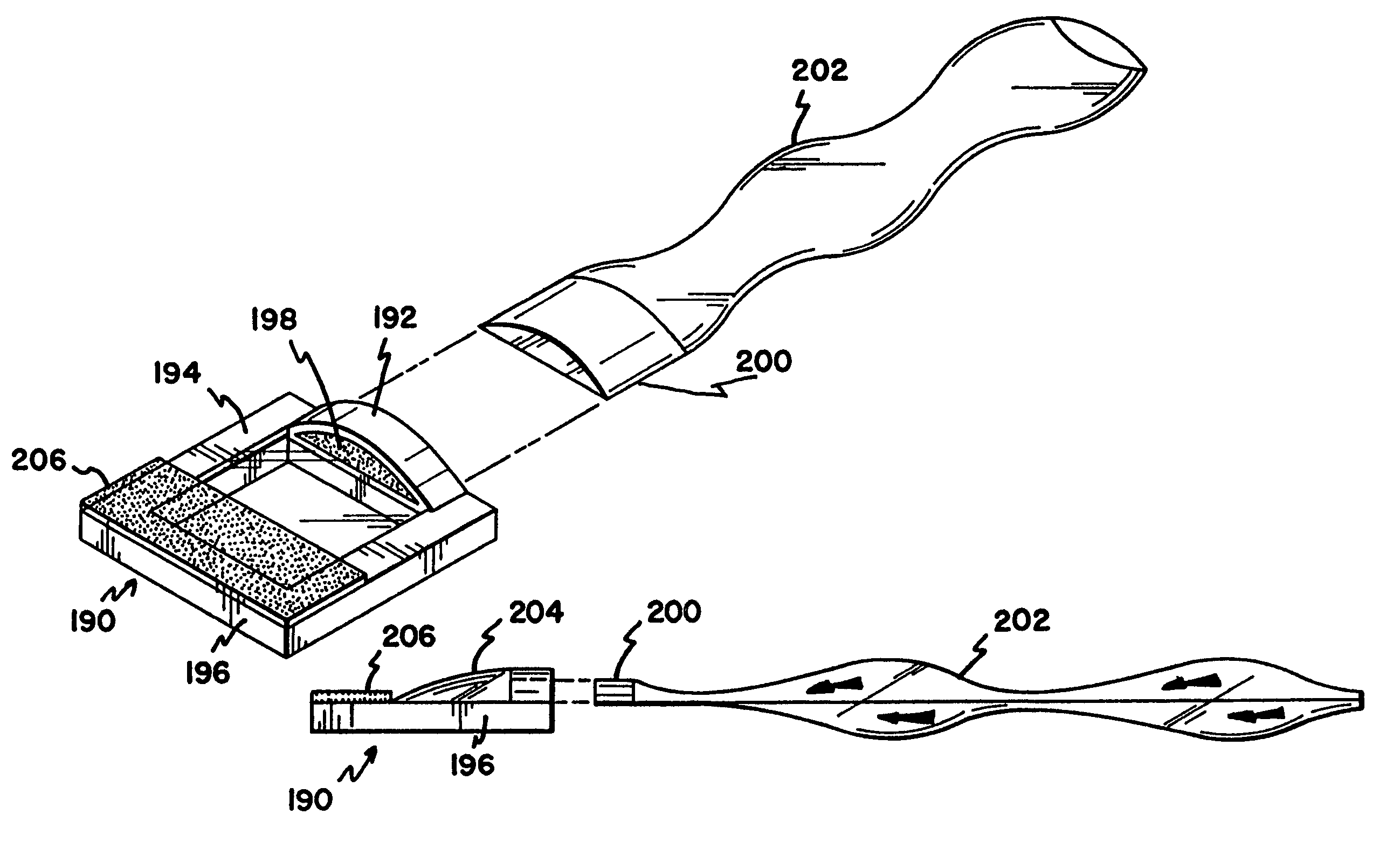
[0041]The present invention is directed to a non-contact wound covering for controlling the local environment at a wound site on a patient. The wound covering protects the wound from contamination by materials from the outside environment and also prevents the wound site from shedding contaminants into the local environment of the patient, i.e. the hospital room. The treatment volume formed over the wound site can be controlled to create an optimal healing environment. The word “wound” as used herein refers generically to surgical incisions, ulcers, or other lesions or breaks in the skin.

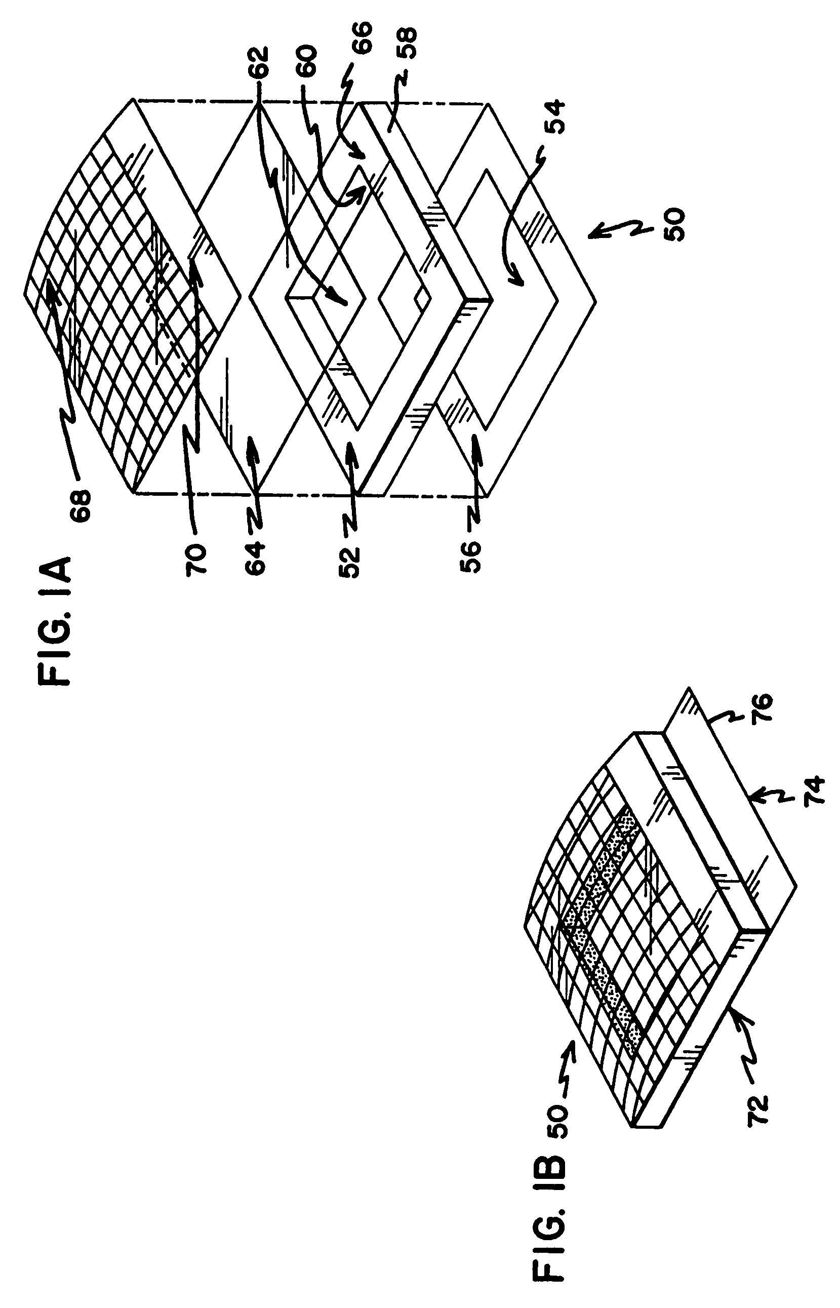
[0042]Each embodiment of the wound covering includes three basic elements. First a vertical wall is provided to encircle the wound area on the surface of the patient's skin. This vertical structure is self supporting and provides an upper surface to support a barrier layer above the level of the wound. This structure is referred to throughout as the peripheral sealing ring. The next element is a bar...


PUM


Abstract

A non-contact wound covering for covering a wound includes a peripheral sealing ring. The peripheral sealing ring is covered by a barrier layer and this assembly is attached to the skin with an adhesive. The barrier layer and peripheral sealing ring together define a treatment volume over the wound. Treatment fluid is introduced into the treatment volume through an inlet, and is exhausted therefrom through an outlet or an exhaust filter.

Description

PRIORITY[0001]This is a continuation of U.S. patent application Ser. No. 10 / 246,605, filed Sep. 17, 2002, which is a continuation of U.S. patent application Ser. No. 09 / 772,025, filed Jan. 29, 2001, now U.S. Pat. No. 6,465,708, which is a continuation of U.S. patent application Ser. No. 09 / 411,802, filed Oct. 4, 1999, now U.S. Pat. No. 6,241,697, which is a continuation of U.S. patent application Ser. No. 09 / 272,181, filed Mar. 18, 1999, now U.S. Pat. No. 5,961,480, which is a divisional of U.S. patent application Ser. No. 08 / 999,353, filed Dec. 29, 1997, now U.S. Pat. No. 5,947,914, which is a continuation of Ser. No. 08 / 356,325, filed Feb. 21, 1995, now abandoned, which is a 35 U.S.C. §371 priority application of PCT International Application Serial No. PCT / US93 / 05876, filed Jun. 18, 1993, which is a continuation-in-part of, and claims priority from, U.S. patent application Ser. No. 07 / 900,656, filed Jun. 19, 1992, now abandoned.BACKGROUND OF THE INVENTION[0002]1. Field of the Inv...

Claims


Application Information

Patent Timeline
Patent Type & Authority Patents(United States)
IPC IPC(8): A61F13/00
CPCA61F13/0203
Inventor AUGUSTINE, SCOTT D.
Owner 3M INNOVATIVE PROPERTIES CO
Why Eureka
Try Eureka