Supercharge Your Innovation With Domain-Expert AI Agents!

Molded motor

a technology of molded motors and heat-conducting components, which is applied in the direction of magnetic circuit rotating parts, magnetic circuit shapes/forms/construction, windings, etc., can solve the problems of insufficient dissipation of heat generated by the plurality of winding portions of stators, complicated mounting structures of heat-conducting components, etc., to achieve the effect of simplifying the structure of heat-conducting components, reducing the waterproof property of molded parts, and reducing the number of winding

Inactive Publication Date: 2011-04-19
SANYO DENKI CO LTD
View PDF6 Cites 14 Cited by
  • Summary
  • Abstract
  • Description
  • Claims
  • Application Information

AI Technical Summary

Benefits of technology

[0004]An object of the present invention is to provide a molded motor with a simple structure facilitating installation of a heat-conducting member in a molded portion.
[0020]Preferably, a plurality of screw holes may be formed in one of the load-side end bracket and the non-load-side end bracket, a plurality of screw through-holes may be formed in the other of the load-side end bracket and the non-load-side end bracket, and the non-load-side end bracket and the load-side end bracket are coupled to each other via the stator by a plurality of screws passing through the plurality of screw through-holes and screwed into the plurality of screw holes. With this configuration, the stator core and the non-load-side end bracket are electrically connected to each other through the heat-conducting member, the load-side end bracket, and the screws. It is thus not necessary to provide separate earth conductors for the stator core and the non-load-side end bracket.

Problems solved by technology

The conventional molded motors have a complicated mounting structure for the heat-conducting member, and also are laborious to produce.
In addition, heat generated from the plurality of winding portions of the stator may not be sufficiently dissipated.

Method used


Image

  • Molded motor
  • Molded motor
  • Molded motor

Examples


Embodiment Construction

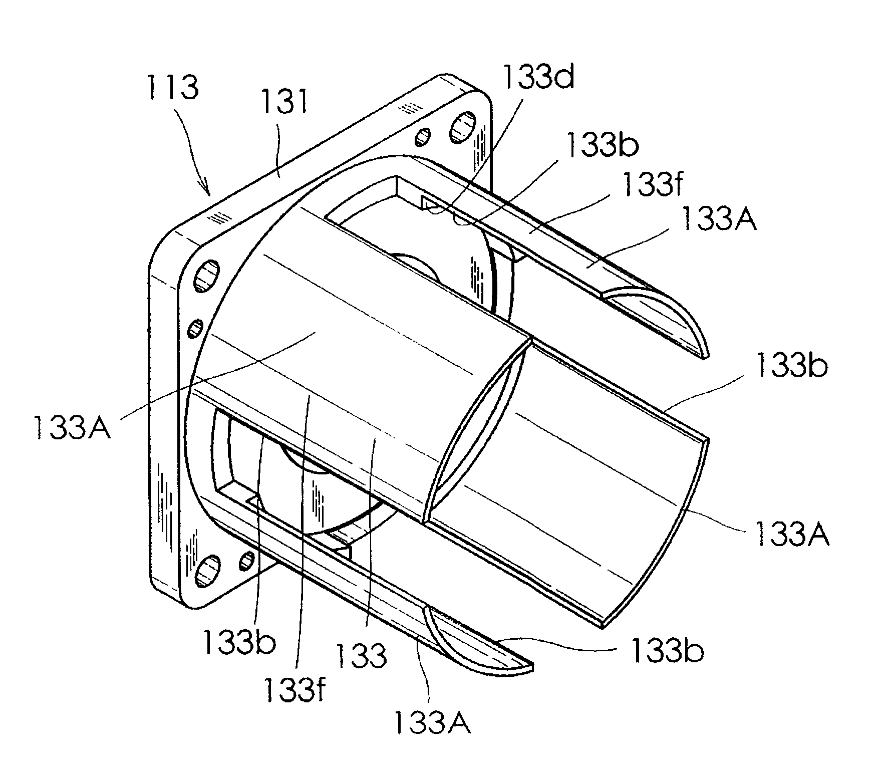
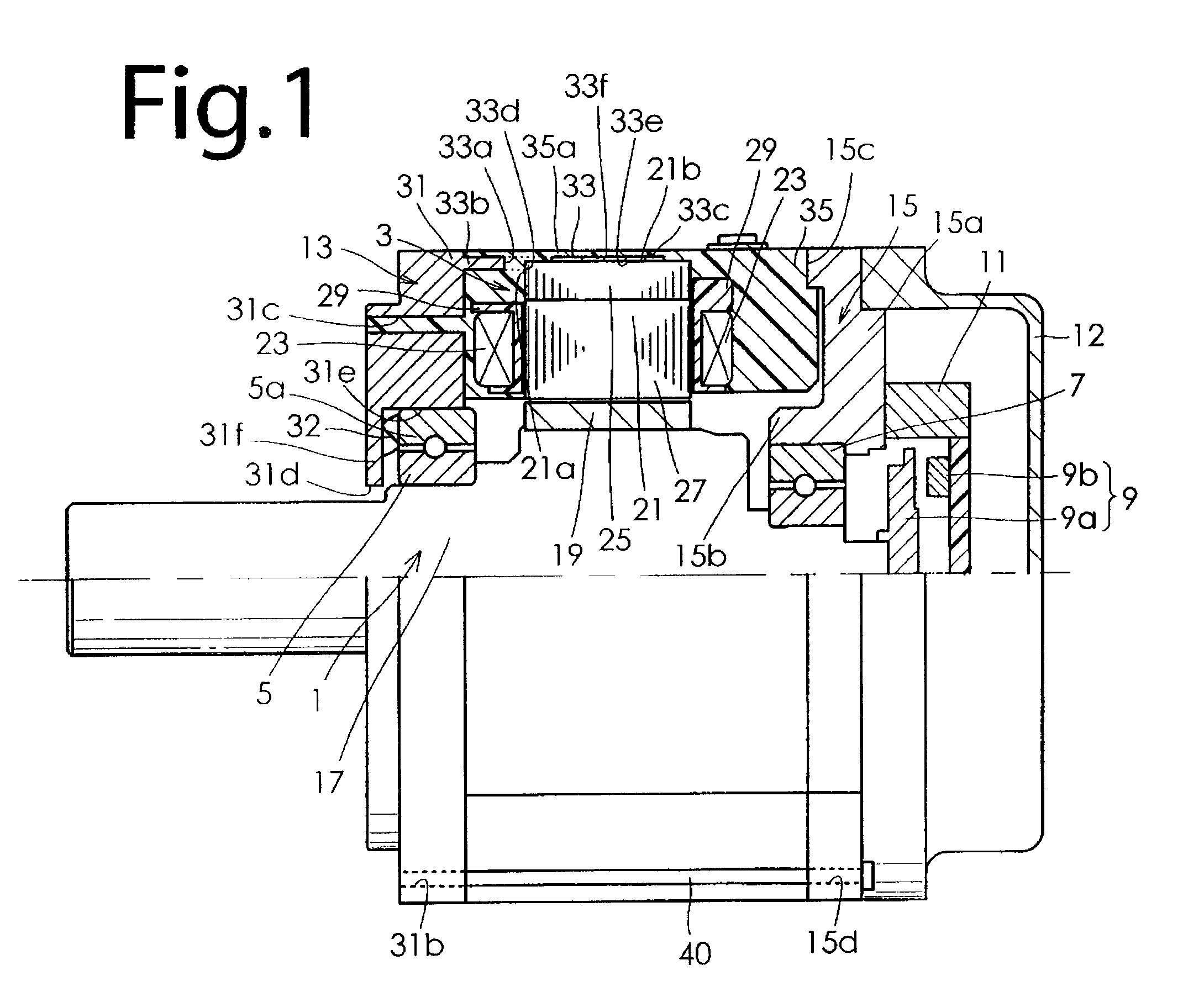
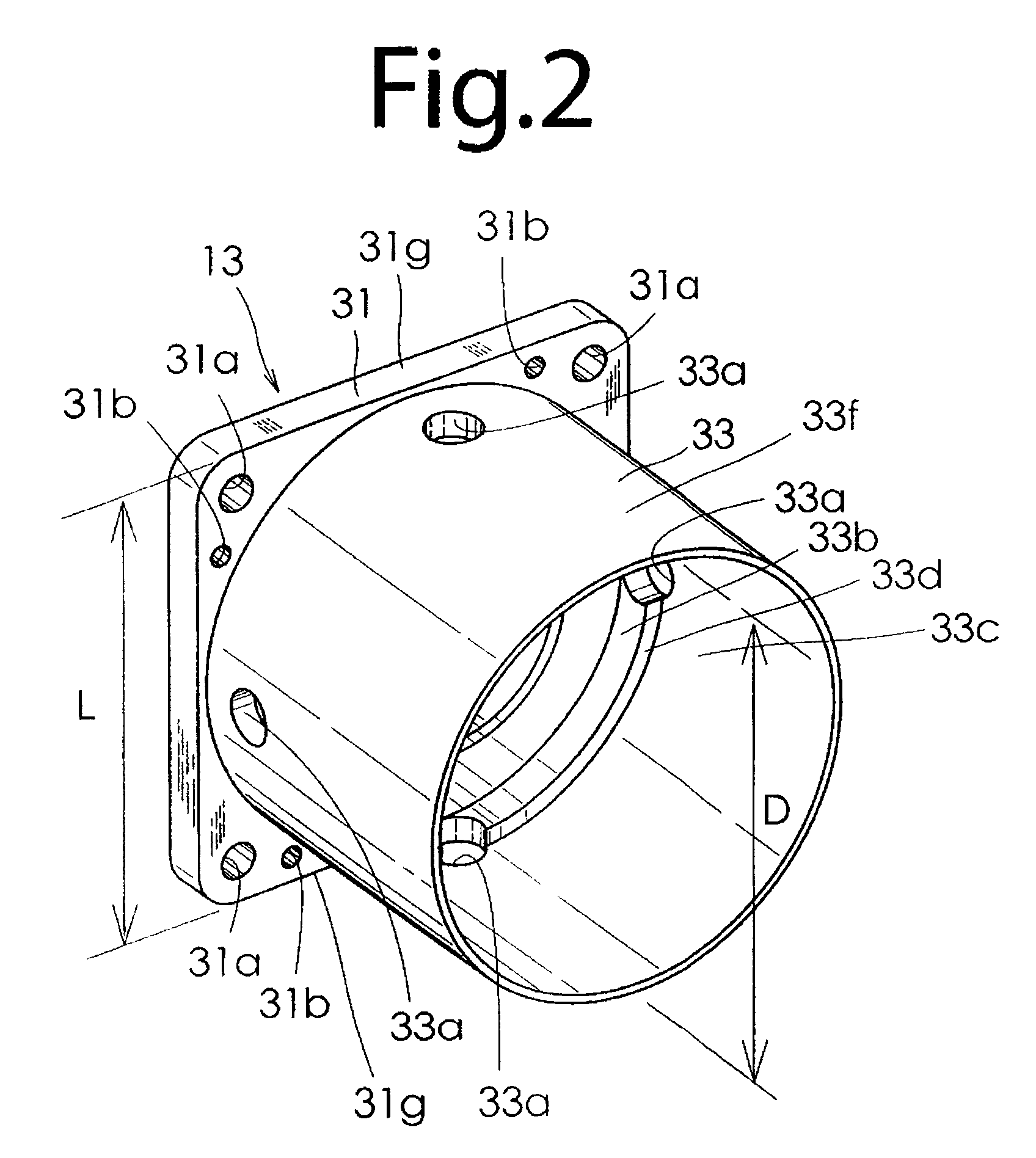
[0031]Now, embodiments of the present invention will be hereinafter described in detail with reference to the drawings. FIG. 1 shows a molded motor according to an embodiment of the present invention with a half of the molded motor cut away. As shown in FIG. 1, the molded motor according to the embodiment comprises a rotor 1, a stator 3, a pair of ball bearings 5 and 7, a magnetic rotary encoder 9 which serves as a rotational position detector, a cover member 11, a casing 12, a bracket assembly 13 including a load-side end bracket 31 and a heat-conducting member 33, and a non-load-side end bracket 15. The rotor 1 includes a shaft 17 supported rotatably by the pair of bearings 5, 7 and rotor magnetic poles 19 secured to the outer periphery of the shaft 17. The rotor magnetic poles 19 include a plurality of permanent magnets secured to the outer peripheral portion of the shaft 17.

[0032]The stator 3 includes a stator core 21, a plurality of winding portions 23, and a molded portion 35....


PUM


Abstract

A molded motor is provided that allows for ready installation of a heat-conducting member therein and is capable of improving dissipation of heat generated from the stator. The heat-conducting member is integrally formed with a load-side end bracket. The heat-conducting member includes a stopper surface that contacts an end surface of a stator core in the axial direction of a shaft, and an extended portion extending from the stopper surface toward a non-load-side end bracket to contact an outer peripheral surface of the stator core. The heat-conducting member is embedded in a molded portion with the stopper surface contacting the end surface of the stator core and the extended portion contacting the outer peripheral surface of the stator core.

Description

TECHNICAL FIELD[0001]The present invention relates to a molded motor including a metal heat-conducting member that positively conducts heat generated from a stator with a plurality of winding portions to a load-side end bracket.BACKGROUND ART[0002]Japanese Patent No. 3845861 has proposed a motor including a cylindrical heat-conducting member made of aluminum and disposed on an outer peripheral portion of a stator core and contacting the stator core and a load-side end bracket. With the heat-conducting member, heat generated from a plurality of winding portions is conducted from the stator core to the load-side end bracket via the heat-conducting member to be dissipated to the outside. Japanese Patent No. 3780164 has proposed a molded motor in which a main portion of a stator is molded from a resin and a heat-conducting member of a metal bar is embedded in the resin and is in contact with a load-side end bracket but not with a stator core. With the heat-conducting member of a metal b...

Claims


Application Information

Patent Timeline
Patent Type & Authority Patents(United States)
IPC IPC(8): H02K1/04
CPCH02K5/08H02K9/22H02K5/15H02K9/223H02K3/44
Inventor MIYASHITA, TOSHIHITOHIOKI, HIROSHICHIKYU, MASAKAZU
Owner SANYO DENKI CO LTD
Features
  • R&D
  • Intellectual Property
  • Life Sciences
  • Materials
  • Tech Scout
  • Unparalleled Data Quality
  • Higher Quality Content
  • 60% Fewer Hallucinations
Learn More