Airtight container and display device using the airtight container, and manufacturing method therefor

a technology of airtight containers and display devices, which is applied in the manufacture of electrode systems, electric discharge tubes/lamps, discharge tubes luminescnet screens, etc., can solve the problems of gaps between inner wall surfaces of grooves and wirings, and achieve the effect of suppressing the air tightness at the joint section

Inactive Publication Date: 2011-04-19
CANON KK
View PDF5 Cites 9 Cited by
  • Summary
  • Abstract
  • Description
  • Claims
  • Application Information

AI Technical Summary

Benefits of technology

[0007]In a case where wirings are arranged inside grooves formed on a surface of a substrate so as to extend, and a pair of substrates are joined airtightly on the groove, this causes a difference between a thermal expansion coefficient of a substrate material and a thermal expansion coefficient of a wiring material filled inside the grooves, or sintering shrinkage of the wiring material. For that reason, there were cases of causing gaps between inner wall surfaces of the grooves and the wirings. As a result, there were cases where the airtightness of the joint portions was reduced.
[0013]As a result, even if gaps are caused between inner walls of the grooves and the wirings arranged inside the grooves, the reduction of the airtightness at the joint section may be suppressed.

Problems solved by technology

For that reason, there were cases of causing gaps between inner wall surfaces of the grooves and the wirings.

Method used


Image

  • Airtight container and display device using the airtight container, and manufacturing method therefor
  • Airtight container and display device using the airtight container, and manufacturing method therefor
  • Airtight container and display device using the airtight container, and manufacturing method therefor

Examples


examples

[0051]Hereinafter, the present invention is described with reference to more specific examples.

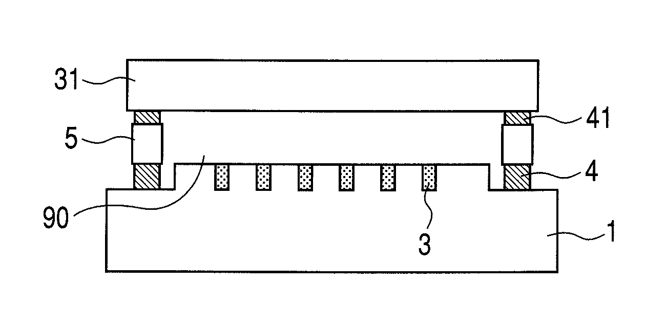
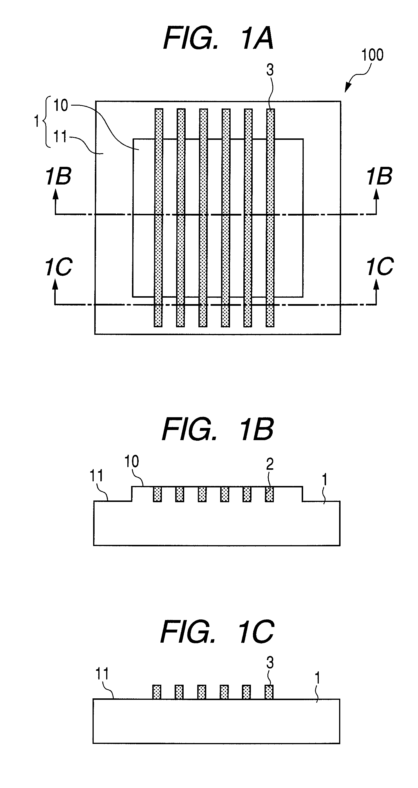
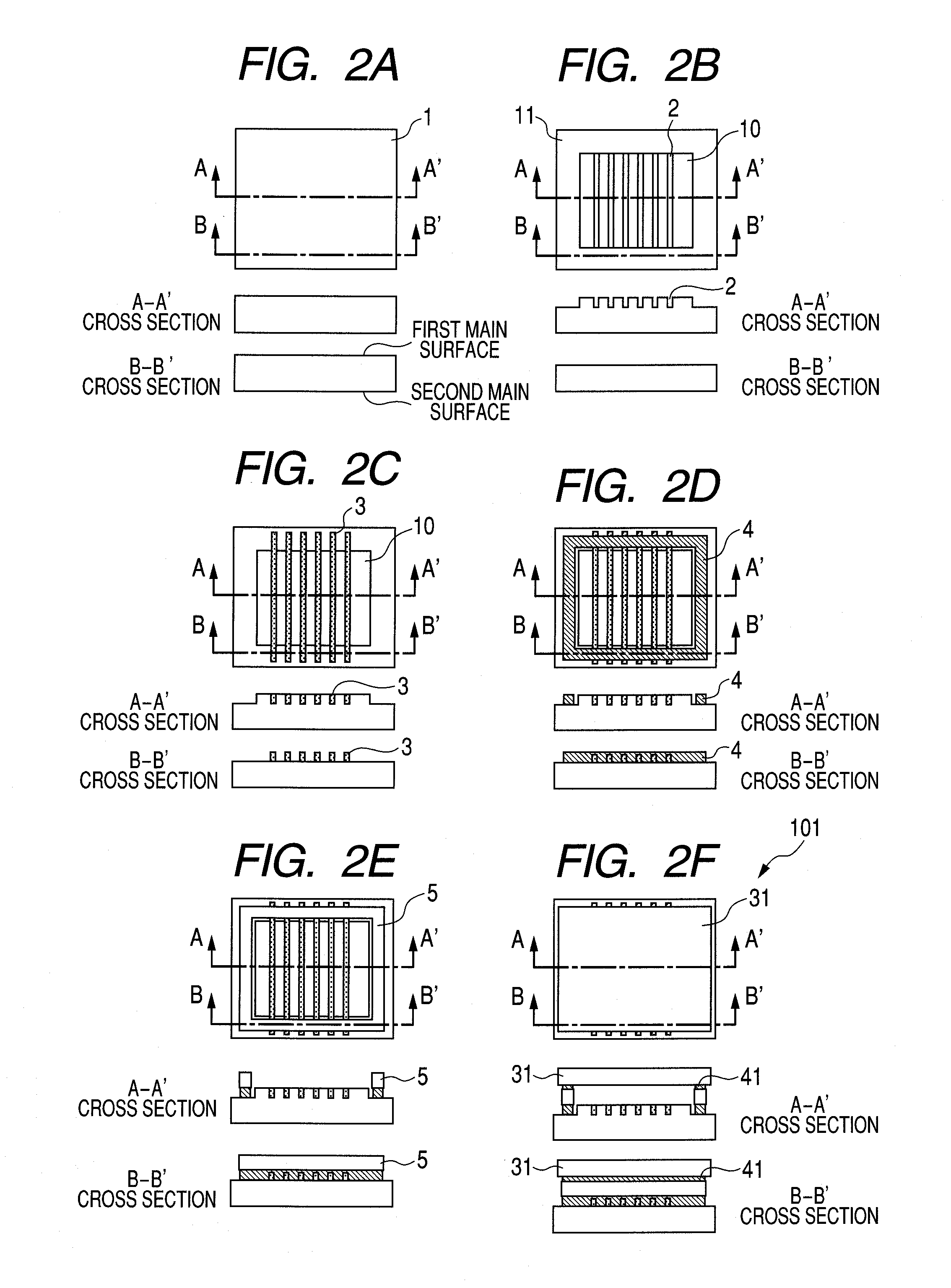
[0052]Examples in which the present invention is used are described with reference to FIGS. 2A to 2F, FIGS. 3A to 3C, and FIGS. 5A and 5B. In this example, a display panel is formed, which uses an airtight container including a wiring substrate 100 provided with surface conduction electron emission devices 15 as illustrated in FIGS. 5A and 5B. Note that, for simplification of description, FIGS. 2A to 2F and FIGS. 3A to 3C were used. However, in this example, to a structure illustrated in FIGS. 2A to 2F and FIGS. 3A to 3C, the electron emission devices 15 and wirings 40 are added as illustrated in FIGS. 5A and 5B.

[0053](Step 1)

[0054]On a surface of a glass substrate 1 having a size of 300 mm×350 mm (vertical×lateral) and a thickness of 2.8 mm, Pt film is formed on an entire surface into a thickness of 40 nm by a sputtering method. Subsequently, patterning is carried out by a photolithograph...


PUM


Abstract

An airtight container includes a first substrate and a second substrate facing the first substrate and joined thereto using joint members. The first substrate has a groove extending on a surface of the first substrate and a wiring provided along a direction of the extended groove. The wiring includes a section inside and along the groove and a section outside the groove and extending from the section inside the groove, and the first substrate includes joint members provided on and across the section of the wiring outside the groove. In addition, a frame is joined on the second substrate by second joint members and is interposed between the first substrate and the second substrate. The frame is joined to the first substrate by the first joint members.

Description

BACKGROUND OF THE INVENTION[0001]1. Field of the Invention[0002]The present invention relates to an airtight container and a display device in which a wiring substrate having wirings arranged inside grooves formed on a surface of the wiring substrate is used.[0003]2. Description of the Related Art[0004]Examples of a flat panel display include a liquid crystal display (LCD), a plasma display (PDP), an inorganic EL display, an organic EL display (OLED), and a field emission display (FED). Those flat panel displays are provided with a flat-shaped airtight container, and a plurality of wirings are formed inside thereof (internal space). In the LCD, inside the airtight container, a liquid crystal material is disposed, and in PDP, discharge gas is disposed inside the airtight container. In the EL display, predetermined gas such as nitrogen is disposed inside the airtight container, or a pressure inside the airtight container is kept lower than the atmospheric pressure. Besides, in FED, th...

Claims


Application Information

Patent Timeline
Patent Type & Authority Patents(United States)
IPC IPC(8): H01J1/62
CPCH01J9/02H01J9/241H01J9/32H01J17/04H01J17/16H01J17/186H01L51/5237H01J29/861H01J29/90H01L27/3288H01J29/04H01J2329/02H01J2329/861H01J2329/90H10K59/179H10K59/8722H10K50/8426
Inventor SUZUKI, YOSHIOISHIWATA, KAZUYA
Owner CANON KK
Why Eureka
Try Eureka