
Modulated disk lock clock and methods for using such

a technology of moduled disks and lock clocks, applied in the direction of digital recording, recording signal processing, instruments, etc., can solve the problems of increasing or decreasing, and the loss of lock performance is becoming increasingly difficult to m

Inactive Publication Date: 2011-04-19
AVAGO TECH INT SALES PTE LTD
View PDF44 Cites 20 Cited by
  • Summary
  • Abstract
  • Description
  • Claims
  • Application Information

AI Technical Summary

Benefits of technology

This approach reduces frequency offset on an individual bit basis, enhances loss of lock performance, and enables smoother clock adjustments, improving data access accuracy and reliability across magnetic storage media.

Problems solved by technology

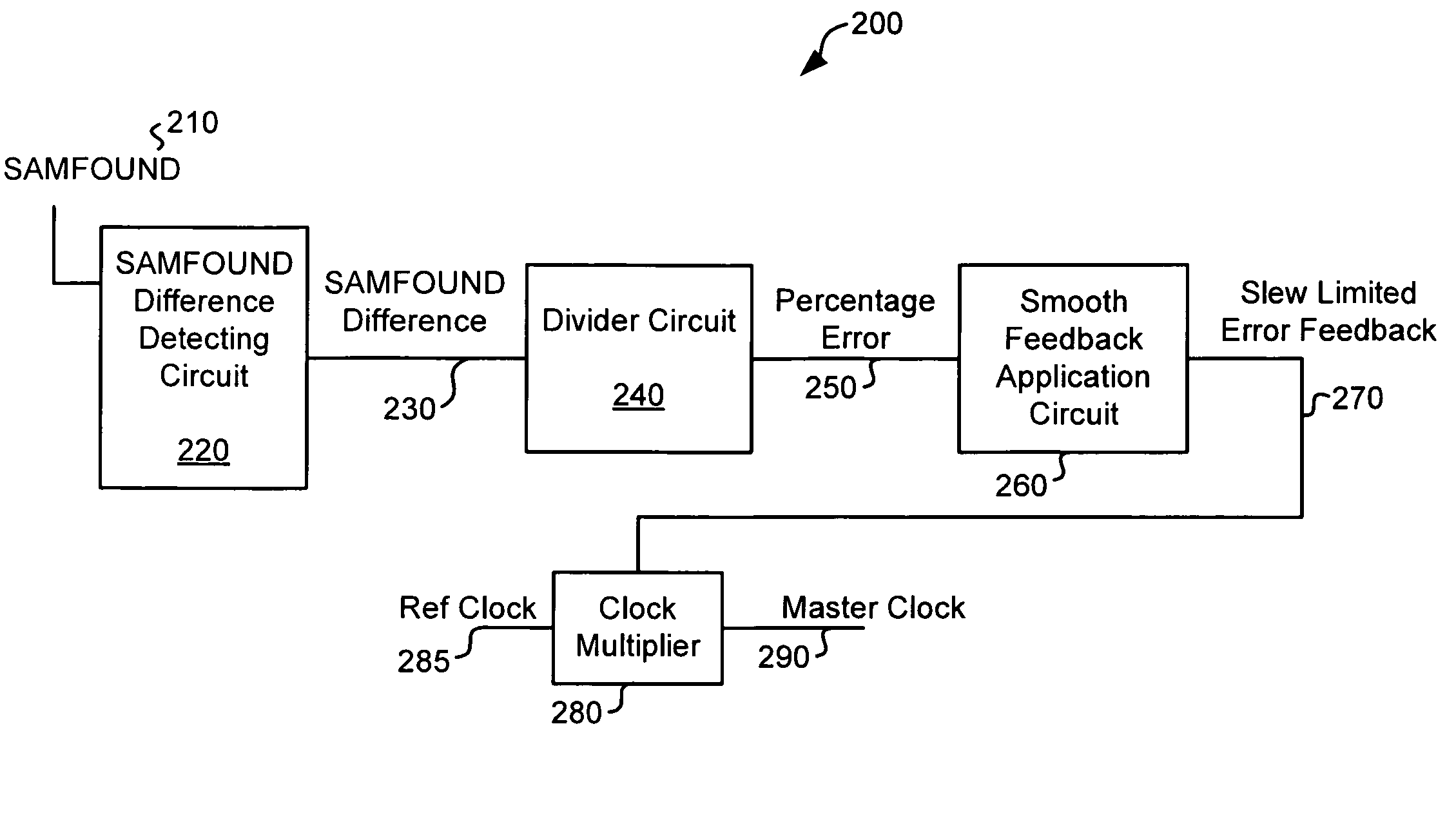
Where the disk lock clock is not properly locked, it is increased or decreased by an error amount indicated by the difference between the expected timing between consecutive SAMFOUND signals and the actual timing.
However, as data detector technology continues to improve which allows for operation at lower signal to noise ratios, the loss of lock performance are becoming increasingly difficult to meet.

Method used


Image

  • Modulated disk lock clock and methods for using such
  • Modulated disk lock clock and methods for using such
  • Modulated disk lock clock and methods for using such

Examples


Embodiment Construction

[0019]The present invention is related to systems and methods for accessing a magnetic storage medium, and more particularly to systems and methods for controlling access to a magnetic storage medium.

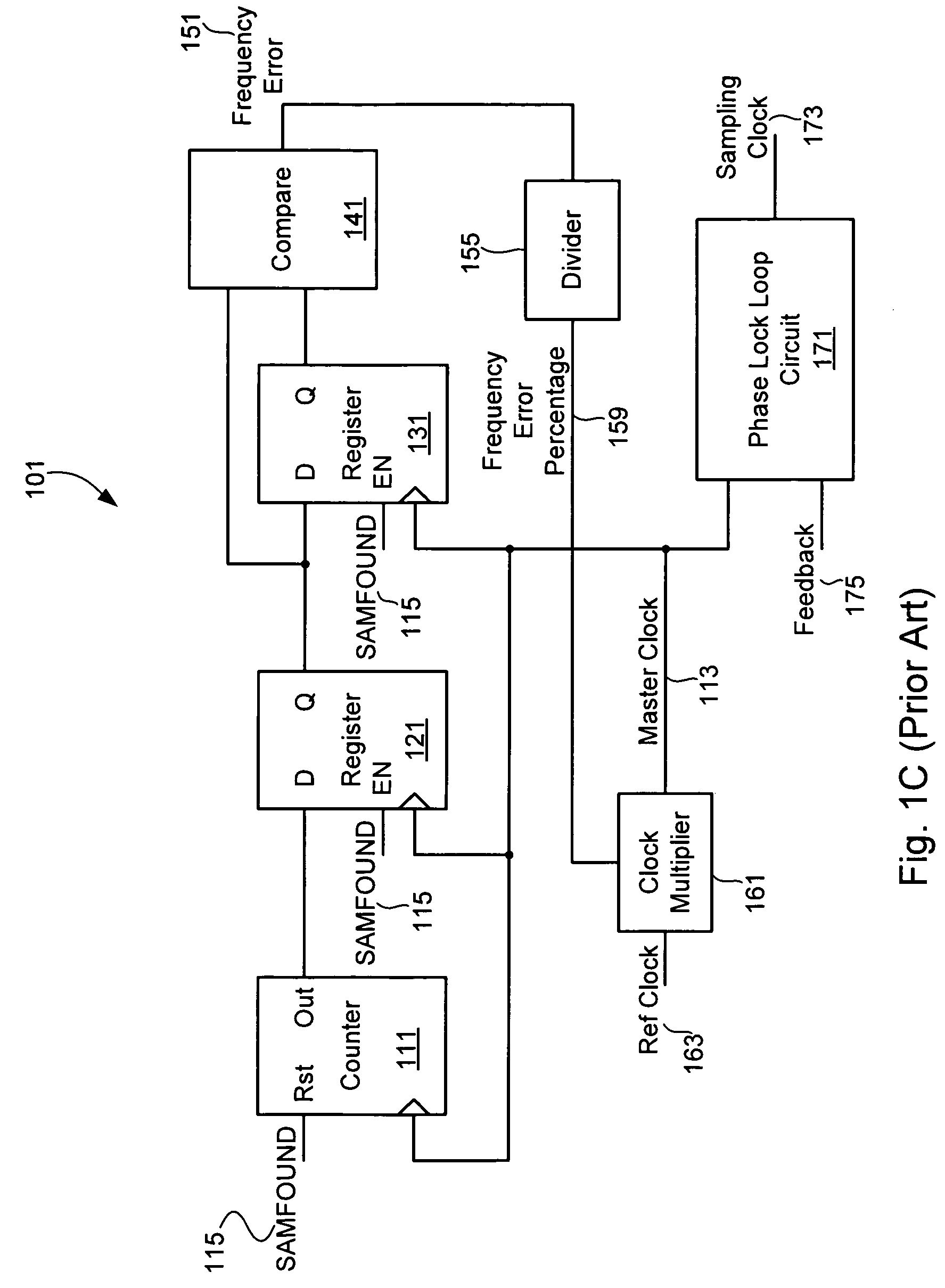
[0020]Turning to FIG. 1C, a prior art disk lock clock circuit 101 is shown. Disk lock clock circuit 101 includes a counter that is incremented on each rising edge of a master clock 113, and is reset each time a SAMFOUND signal 115 is asserted. In addition, each time SAMFOUND signal 115 is asserted, the count value from counter 111 is stored to a register 121 and the value previously stored in register 121 is stored in a register 131. Thus, register 131 holds a count value associated with the preceding SAMFOUND signal 115, and register 121 holds a count value for the current SAMFOUND signal 115. The count from each of registers, 131 are compared by a comparator 141. The output of comparator 141 is a frequency error output 151 that indicates whether the count between successive SAMFOUND s...


PUM

PropertyMeasurementUnit
movement rateaaaaaaaaaa
timeaaaaaaaaaa
frequencyaaaaaaaaaa

Abstract

Various embodiments of the present invention provide systems and methods for controlling access to a magnetic storage medium. As one example, a method for controlling access to a storage medium is disclosed that includes calculating a point to point error amount, and generating a incremental error value based at least in part on the point to point error amount. The incremental error value is applied incrementally across a defined number of clock cycles.

Description

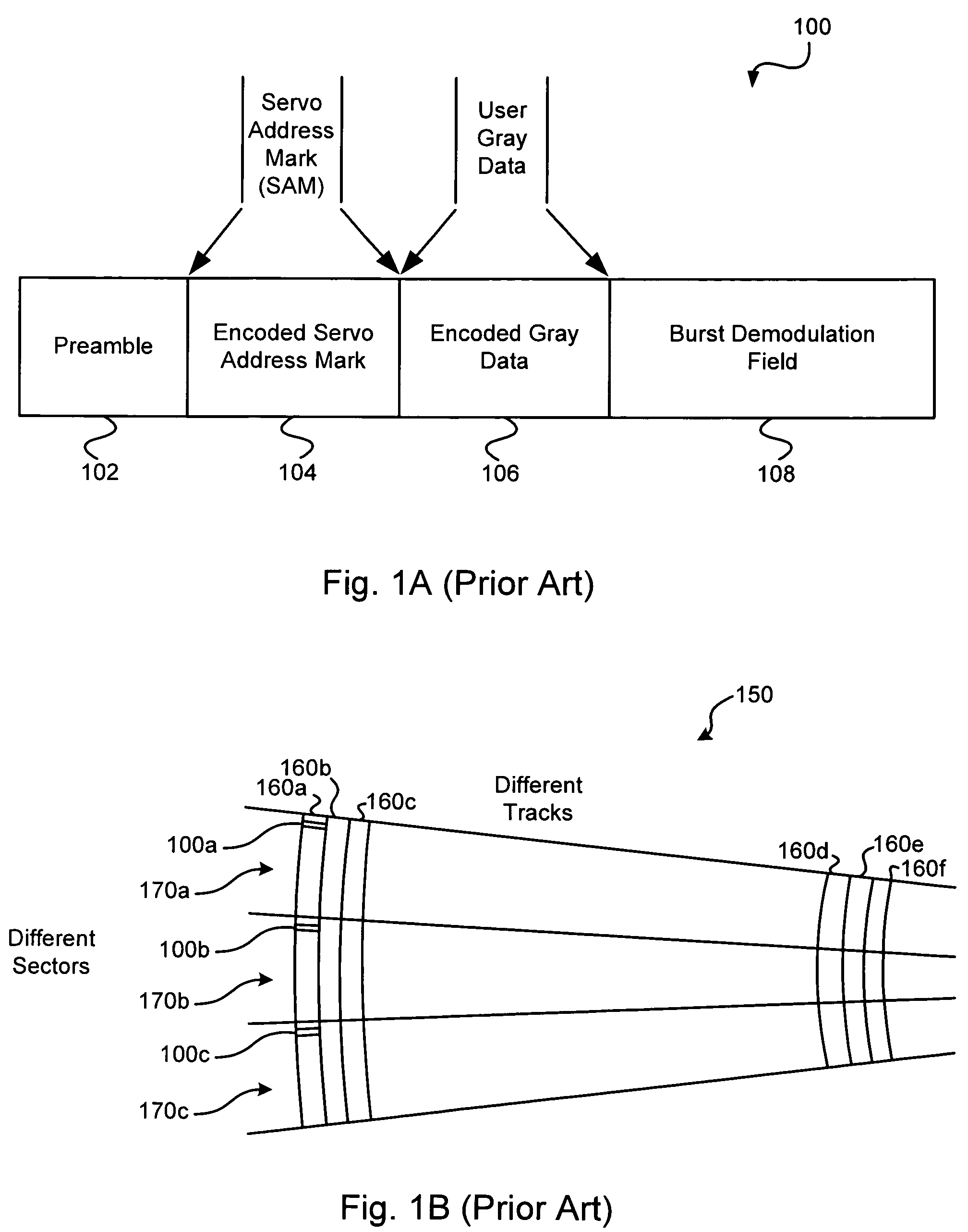
BACKGROUND OF THE INVENTION[0001]The present invention is related to systems and methods for accessing a magnetic storage medium, and more particularly to systems and methods for controlling access to a magnetic storage medium.[0002]A magnetic storage device typically include a storage medium that carries both stored data and synchronization information. The synchronization information is placed at intermittent locations across the storage medium and is periodically accessed to aid in identifying the location of a read / write head assembly in relation to the storage medium. FIG. 1A depicts an exemplary set of synchronization information generally referred to as a servo data sector 100. As shown, servo data sector 100 may include a preamble pattern 102 which allows the system to recover the timing and gain of the written servo data. Preamble pattern 102 is typically followed by a servo address mark (SAM) 104 which is the same for all servo sectors. SAM 104 is then followed by encoded ...

Claims


Application Information

Patent Timeline
Patent Type & Authority Patents(United States)
IPC IPC(8): G11B5/09G11B27/36
CPCG11B20/10222G11B20/14G11B2220/2516G11B2020/1484G11B2020/1476
Inventor GRUNDVIG, JEFFREY P.RAUSCHMAYER, RICHARD
Owner AVAGO TECH INT SALES PTE LTD
Learn More