Device for compensating radio frequency distortion in orthogonal frequency division multiplexing transmission system and method thereof

a technology transmission system, applied in the field of orthogonal frequency division multiplexing transmission system and device for compensating radio frequency distortion, can solve the problems of not being easily used in portable terminal, not being used in potable terminals in which power consumption is very important, and signal distortion occurring

Active Publication Date: 2011-04-19
ELECTRONICS & TELECOMM RES INST
View PDF13 Cites 1 Cited by
  • Summary
  • Abstract
  • Description
  • Claims
  • Application Information

AI Technical Summary

Benefits of technology

[0016]The present invention has been made in an effort to provide a device for processing frequency domain data before an inverse fast Fourier transform unit, and simply and efficiently compensating a distortion caused by a digital / analog converter at a frequency domain in an orthogonal frequency division multiplexing transmission system, and a method thereof.
[0019]In an exemplary method for receiving a digital signal and a symbol synchronization signal of an external modem, using a digital modulator and an inverse fast Fourier transform (IFFT) unit to perform a digital signal process, and compensating a distortion of a radio frequency output to a digital / analog converter in an orthogonal frequency division multiplexing transmission system, a coefficient of an inverse sync function is generated according to the number of transmission data except a sample frequency of an in-phase (I) signal and a quadrature-phase (Q) signal output through the digital modulator, and direct current (DC) and Null signals of the IFFT unit, the generated coefficient of the inverse sync function is multiplied by the signal output through the digital modulator, and the distortion is compensated.
[0020]In an exemplary method for receiving a digital signal and a symbol synchronization signal of an external modem, using a digital modulator and an inverse fast Fourier transform (IFFT) unit to perform a digital signal process, and compensating a distortion of a radio frequency output to a digital / analog converter in an orthogonal frequency division multiplexing transmission system, a coefficient of an inverse sync function is generated according to the number of transmission data except a sample frequency of an in-phase (I) signal and a quadrature-phase (Q) signal output through the digital modulator, and direct current (DC) and Null signals of the IFFT unit, a signal output through the digital modulator is converted into parallel data, the converted data is multiplied by the generated coefficient of the inverse sync function by using a plurality of multipliers, and the distortion is compensated.

Problems solved by technology

In this case, since the transmission signal is converted to the analog signal at a clock frequency which is the same as that of the digital signal, a signal distortion occurs by a sample / hold operation of the digital / analog converter at a radio frequency domain in a band.
Since the above process requires various operations and a radio frequency clock signal, it may not be used in a potable terminal in which power consumption is very important.
However, since a considerable number of operations is required to form a filter in the above method, it is not easily used in the portable terminal.
As described above, in the conventional compensation method at the time domain, a filtering method is used to compensate a signal at the time domain since data at the frequency domain are difficult to be obtained in a conventional digital communication or in a code division multiple access (CDMA) communication, but a considerable number of operations is performed.
However, there is a problem in that the number of operations is increased since the digital filter is used when the interpolation is performed, and a digital / analog converter operating at the radio frequency is used.

Method used


Image

  • Device for compensating radio frequency distortion in orthogonal frequency division multiplexing transmission system and method thereof
  • Device for compensating radio frequency distortion in orthogonal frequency division multiplexing transmission system and method thereof
  • Device for compensating radio frequency distortion in orthogonal frequency division multiplexing transmission system and method thereof

Examples


Embodiment Construction

[0027]In the following detailed description, only certain exemplary embodiments of the present invention have been shown and described, simply by way of illustration. As those skilled in the art would realize, the described embodiments may be modified in various different ways, all without departing from the spirit or scope of the present invention. Accordingly, the drawings and description are to be regarded as illustrative in nature and not restrictive.

[0028]Throughout this specification and the claims which follow, unless explicitly described to the contrary, the word “comprise”, and variations such as “comprises” or “comprising”, will be understood to imply the inclusion of stated elements but not the exclusion of any other elements.

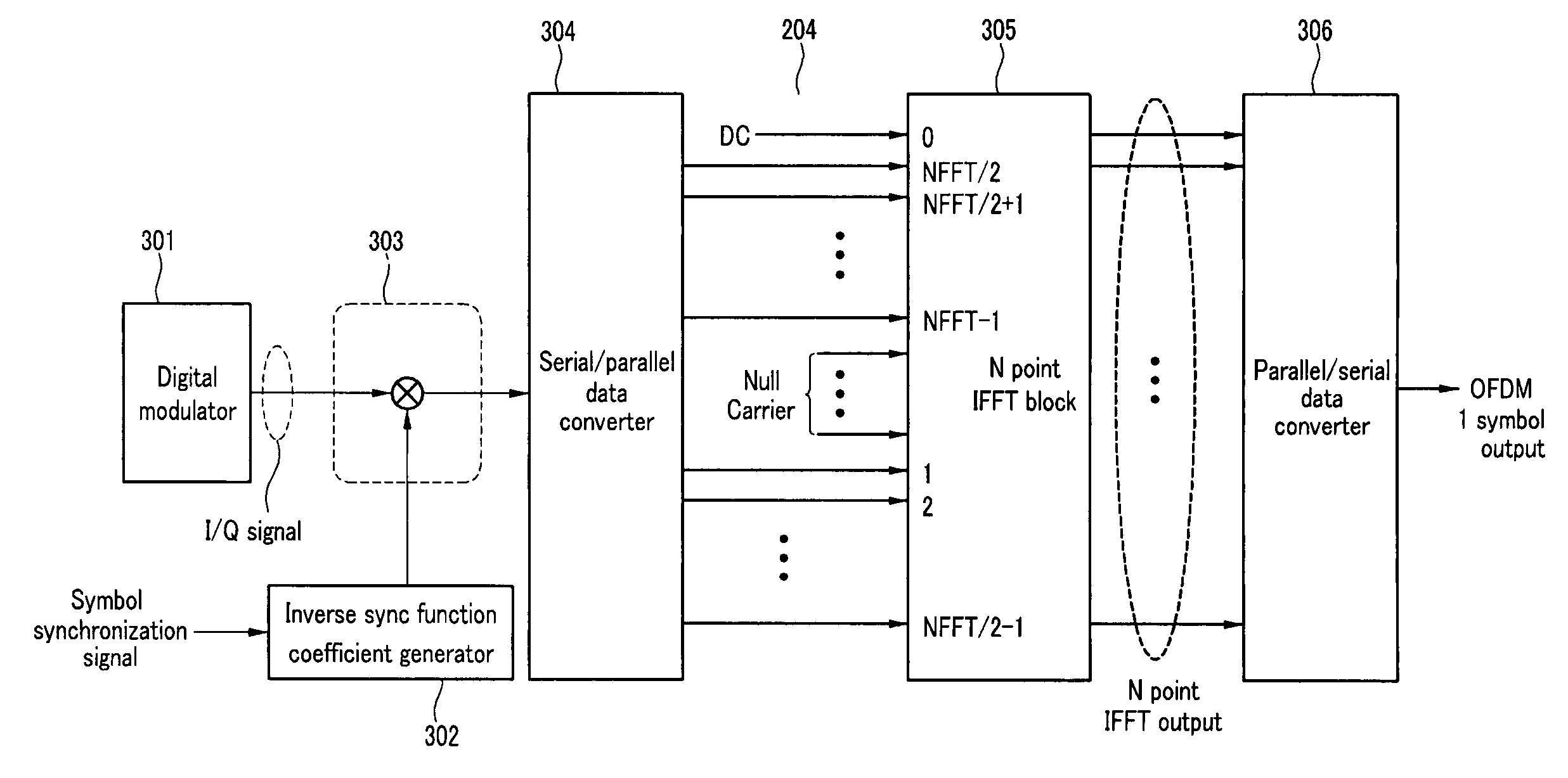
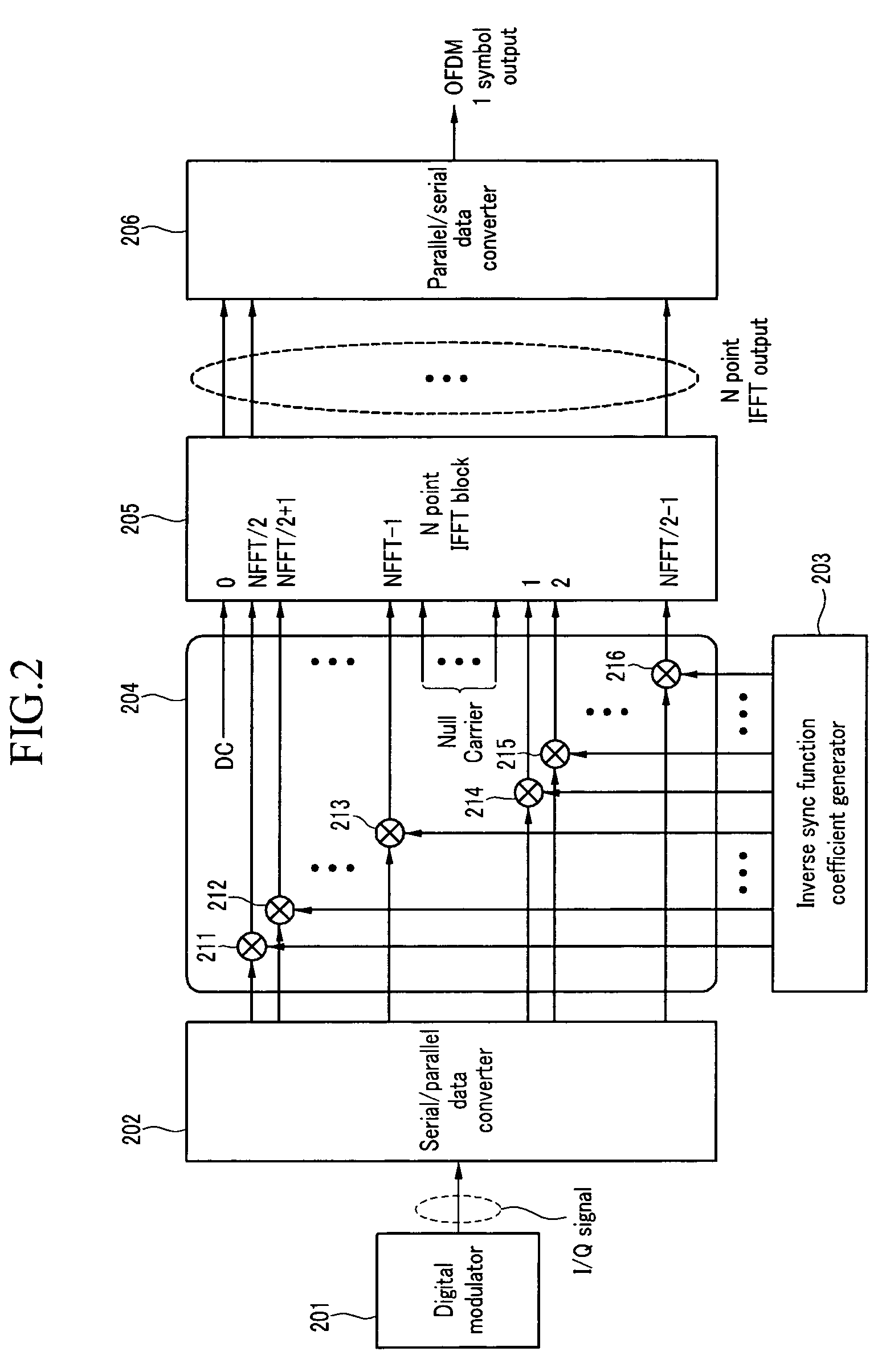
[0029]FIG. 2 shows a diagram of a configuration of a radio frequency distortion compensator of an orthogonal frequency division multiplexing transmission system according to a first exemplary embodiment of the present invention, and the radio frequen...


PUM


Abstract

The present invention relates to a device for compensating a radio frequency distortion caused by a sample / hold operation of a digital / analog converter in an orthogonal frequency division multiplexing (OFDM) transmission system, and a method thereof. In a digital transmission system, an edge frequency signal of a transmission signal band is distorted by a sample / hold operation of a digital / analog converter such that a signal attenuation is generated at a frequency domain by a sync function having a zero point at a sample frequency of a transmission signal. In the present invention, the signal distortion may be compensated by multiplying a coefficient of an inverse sync function by a signal weight value at the frequency domain, and it may be compensated by using a single multiplier and a lookup table storing the coefficient of the inverse sync function.

Description

CROSS-REFERENCE TO RELATED APPLICATION[0001]This application claims priority to and the benefit of Korean Patent Application No. 10-2005-0120870 filed in the Korean Intellectual Property Office on Dec. 9, 2005, the entire contents of which are incorporated herein by reference.BACKGROUND OF THE INVENTION[0002](a) Field of the Invention[0003]The present invention relates to a transmission system in an orthogonal frequency division multiplexing method. More particularly, the present invention relates to a device for compensating a distortion of a transmission signal, the distortion caused by a digital / analog converter, and a method thereof.[0004](b) Description of the Related Art[0005]In an orthogonal frequency division multiplexing transmission system, digital data modulated in various modulation methods are robust against distortions caused by wireless multipaths since orthogonal frequencies are used to transmit the modulated digital data, and a bidirectional communication may be per...

Claims


Application Information

Patent Timeline
Patent Type & Authority Patents(United States)
IPC IPC(8): H04L25/49
CPCH04L27/2628H04L2027/003H04L27/26265H04B1/0475H04L27/2662
Inventor JUNG, JAE-HOKANG, BYUNG-SUKIM, JOON-HYUNGKWON, HEON-KOOKLEE, SUNG-JUNLEE, KWANG-CHUN
Owner ELECTRONICS & TELECOMM RES INST
Why Eureka
Try Eureka