Accumulator of refrigeration cycle system

a technology of accumulator and cycle system, which is applied in the field of accumulator, can solve the problems of reducing the recovery rate of liquid refrigerant in the conventional accumulator, imposing spatial restrictions, and generating noise, and achieves the effect of smooth recovery

Inactive Publication Date: 2011-04-26
LG ELECTRONICS INC
View PDF18 Cites 1 Cited by
  • Summary
  • Abstract
  • Description
  • Claims
  • Application Information

AI Technical Summary

Benefits of technology

[0015]Another object of the present invention is to provide an accumulator which suppresses the generation of bubbles to minimize noise and has high recovery rate of liquid refrigerant.
[0016]A further object of the present invention is to provide an accumulator which allows the positions of outlet and inlet pipes thereof and the flow direction of refrigerant to be easily confirmed from the outside such that it can be easily installed.
[0022]According to the present invention, the accumulator can be installed substantially in a horizontal direction and be operated silently since bubbles are not generated. The liquid refrigerant can be very smoothly recovered to the evaporator.

Problems solved by technology

However, the aforementioned prior art has the following problems.
Therefore, there is a problem in that spatial restrictions are imposed when the accumulator is installed
Further, since a portion of the refrigerant evaporated in the evaporator flows out through the oil recovery hole 7 while flowing along the inlet pipe 5, there is a problem in that bubbles are generated in the liquid refrigerant staying in the chamber 3 to thereby generate noise.
Therefore, there is a problem in that the recovery rate of liquid refrigerant is lowered in the conventional accumulator.

Method used


Image

  • Accumulator of refrigeration cycle system
  • Accumulator of refrigeration cycle system
  • Accumulator of refrigeration cycle system

Examples


Embodiment Construction

[0027]Hereinafter, an accumulator of a refrigeration cycle system according to preferred embodiments of the present invention will be described in detail with reference to the accompanying drawings.

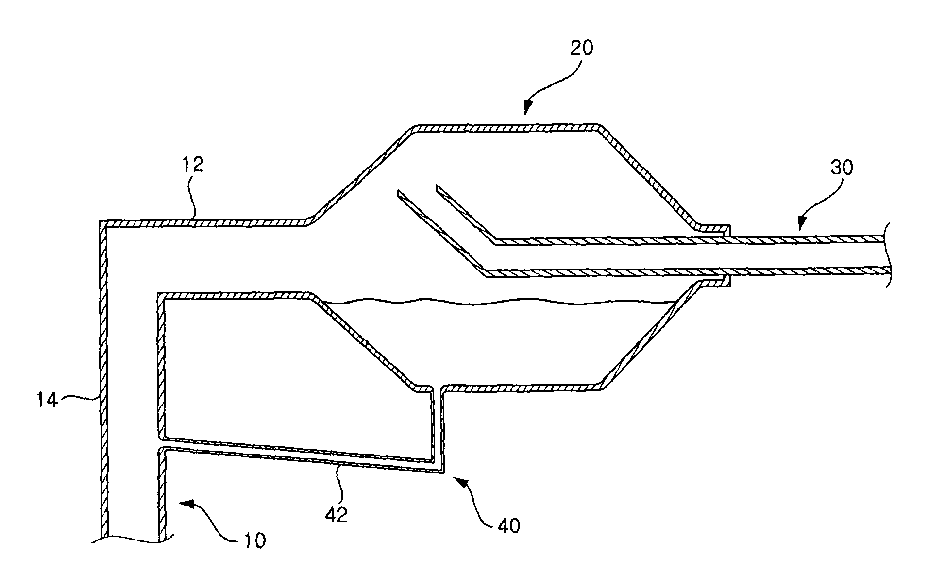
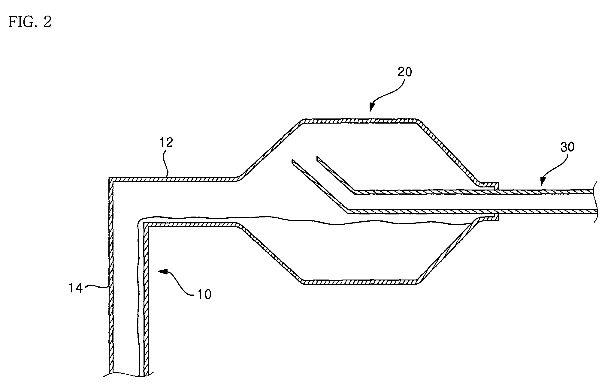
[0028]FIG. 2 is a sectional view of an accumulator according to a first preferred embodiment of the present invention. As shown in the figure, the accumulator of the present invention includes an inlet pipe 10 through which a refrigerant is introduced from an evaporator. The refrigerant from the evaporator flows through the inlet pipe 10.

[0029]The inlet pipe 10 is connected to a chamber 20 installed in a horizontal orientation. The inlet pipe 10 connected to the chamber 20 includes a chamber connecting portion 12 connected substantially horizontally to one end of the chamber 20 and an evaporator connecting portion 14 extending downwardly from the chamber connecting portion 12 and connected to the evaporator.

[0030]A predetermined space is defined within the chamber 20. The other end of the...


PUM


Abstract

An accumulator is provided which is installed between a compressor and an evaporator of a refrigeration cycle system. The accumulator includes an inlet pipe through which refrigerant is introduced from the evaporator, an outlet pipe through which the evaporated refrigerant is delivered to the compressor, and a chamber which is connected to the inlet and outlet pipes and formed with a floor surface at a lower level than connecting portions of the chamber connected to the inlet and outlet pipes. Further, the inlet and outlet pipes are horizontally connected to the chamber.

Description

BACKGROUND OF THE INVENTION[0001]1. Field of Invention[0002]The present invention relates to an accumulator for preventing a liquid refrigerant, which has not been evaporated in an evaporator of a refrigeration cycle system used in a refrigerator, an air conditioner or the like, from being introduced into a compressor, and more particularly, to an accumulator configured to be easily installed and to allow noise to be generated at a minimum level.[0003]2. Description of the Prior Art[0004]A refrigeration cycle system is provided in a machine for generating cold air such as a refrigerator or an air conditioner. In general, the refrigeration cycle system comprises a compressor for compressing a gas refrigerant to high temperature and high pressure, a condenser for converting the high-temperature and high-pressure gas refrigerant compressed in the compressor into a normal-temperature and high-pressure liquid refrigerant, a capillary for converting the normal-temperature and high-pressur...

Claims


Application Information

Patent Timeline
Patent Type & Authority Patents(United States)
IPC IPC(8): F25B43/00F25B43/02
CPCF25B43/006Y10T137/3003F25B43/00
Inventor LYUN-SU, KIM
Owner LG ELECTRONICS INC
Why Eureka
Try Eureka