Air conditioning seat

a seat and air conditioning technology, applied in the field of vehicle air conditioning seats, can solve the problems of inability to achieve the function of the air conditioning seat, difficult to deliver air over a wide range, and closed holes, and achieve the effect of ensuring firm permeability, efficient air distribution, and ensuring the comfort of the seat pad

Active Publication Date: 2011-04-26
TOYOTA BOSHOKU KK +1
View PDF14 Cites 114 Cited by
  • Summary
  • Abstract
  • Description
  • Claims
  • Application Information

AI Technical Summary

Benefits of technology

[0014]By providing the net-like cushion member covering the air blow out port of the air path with the constant elasticity at the surface of the seating portion, it can be avoided that the air blow out port is closed even when the passenger is seated on the air conditioning seat. At the same time, a seating comfort when the passenger is seated is improved. Air is permeable at inside of the net-like cushion member also in the plane direction, and therefore, even when the passenger is brought into close contact with the seating portion, air can be distributed such that air is expanded in a horizontal direction at inside of the net-like cushion member to avoid the passenger. Further, even when the passenger is seated thereon, the firm permeability can be ensured without closing the air blow out port at the seat pad. The net-like cushion member can also promote a heat insulating property of the seat pad by the special structure. Further, a portion of air arranged at inside of the air path is distributed also to the side support portion by passing the communicating path. Thereby, air conditioning at the side support portion can be carried out by way of the net-like cushion member. That is, a total of the surface of the air conditioning seat is provided with a permeability. At this occasion, when the communicating path of communicating the seating portion and the side support portion is formed to pass the back side of the hanging member at inside of the hanging groove, the flow of air flowing at inside of the communicating path is not hampered by the seat cover or the locking piece. Further, the surface according to the invention is a surface relative to the back face and does not signify the surface relative to the inner face (outer face). Therefore, in the seat back, the front face corresponds to the surface and in the seat cushion, the upper face corresponds to the surface.
[0017]The cushion performance of the seat pad against the large load is ensured by the first pad constituting a main body thereof. On the other hand, the second pad is arranged to close the air distributing groove of the first pad while ensuring the through hole constituting the air blow out port. When the second pad is made to be thin-walled, it can be avoided that the seat pad is wastefully thickened. By providing the series of air distributing grooves communicating with the guide hole and expanded planarly in various directions as the air flow path and the through hole of the second pad communicating with the air distributing groove, air guided from the blowing means by way of the guide hole can be blown out from the through holes of the second pad disposed at various positions after having been distributed in various directions efficiently by the air distributing groove. At the side support portion, air flows to inside of the net-like cushion member by way of the communicating groove from the air path of the seating portion and is drawn out to the surface side of the side support portion while being distributed to be expanded pertinently. Thereby, the firm permeability can be ensured while efficiently distributing air over a wide range including the seating portion and the side support portion.
[0018]The hanging member can be constituted by a hanging wire embedded along the hanging groove. In this case, it is preferable to embed the hanging wire to the first pad by insert forming. Further, it is preferable to expose the hanging wire from a bottom face of the hanging groove only at a portion of the cover seat locked by the locking piece. According thereto, a portion of locking the cover seat can freely be designed while firmly holding the hanging wire. Further, the hanging wire formed by inserting forming can be exposed by only cutting the hanging groove, and therefore, fabrication thereof is also facilitated. At this occasion, it is necessary to cut the bottom face of the hanging groove more or less until the back side of the hanging wire such that the locking piece of the cover seat can easily be locked. Hence, when the communicating groove is formed on the back side of the exposed portion of the hanging wire, time and labor of purposely forming the communicating groove at other than the exposed portion of the hanging wire can be saved, and a portion of a space of the communicating groove can effectively be utilized also as a space for locking, and therefore, the constitution is efficient.

Problems solved by technology

Thereby, there is a concern that the through hole is closed by the body of a passenger and a function as the air conditioning seat cannot be achieved.
Thereby, even when the net-like cushion member is air permeable in the plane direction, it is difficult to deliver air over a wide range.
Thereby, ventilation is not efficient, which amounts to also a large-sized formation of the vehicular seat.
Thereby, a flow of air flowing at inside of the extended space is hampered by the seat cover, the locking piece, the resin plate, and the locking metal piece.
Thereby, air cannot smoothly be made to flow to the locking portion of the cover seat and permeability at a center portion of the vehicular seat is extremely deteriorated.
Further, a position of arranging the blowing device is restricted to the side support portion, and therefore, a degree of freedom of designing the vehicular seat is low.
A portion of making air flow to the net-like cushion member is disposed only at the groove portion, and therefore, even when the net-like cushion member is permeable in the plane direction, it is difficult to deliver air over a wide range including the seating portion.
The permeable layer is covered by a seat cover which is difficult to be permeable.
The vehicular seat does not achieve a permeable seating face.

Method used


Image

  • Air conditioning seat
  • Air conditioning seat
  • Air conditioning seat

Examples


Embodiment Construction

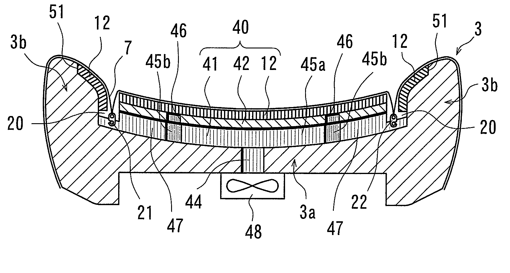
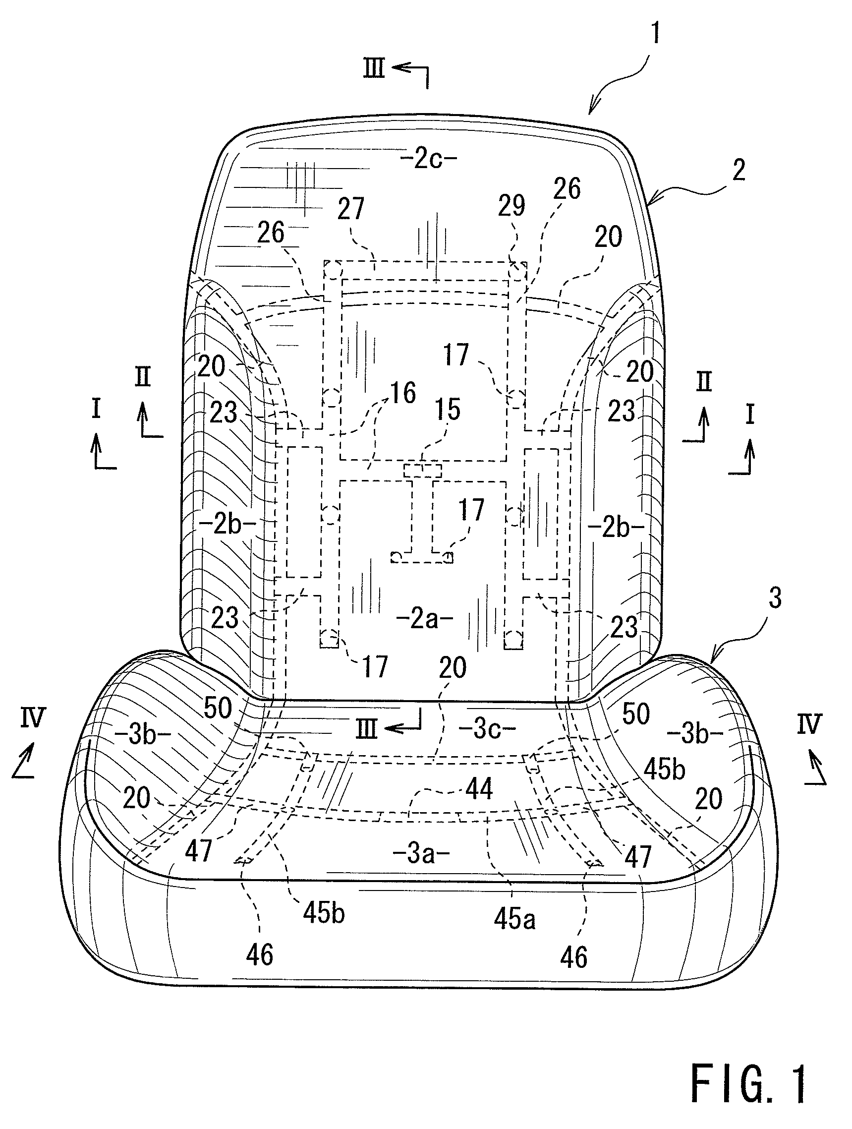
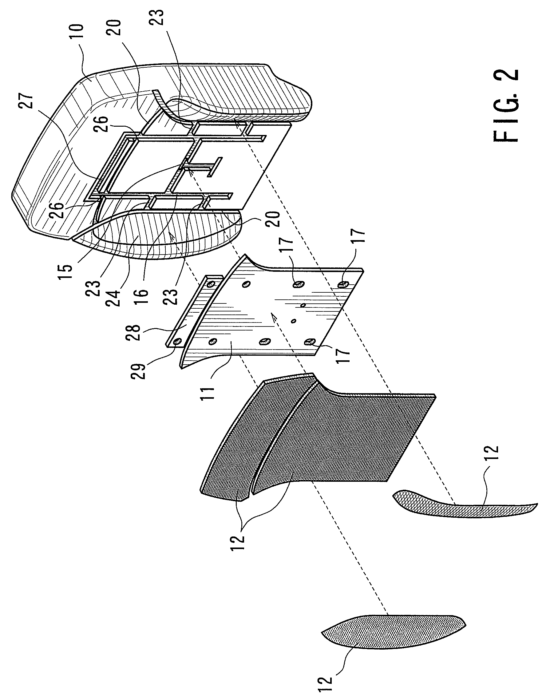
[0028]Air conditioning seat 1 is a vehicular seat mounted to a vehicle of an automobile or the like. As shown by FIG. 1, the air conditioning seat 1 includes a seat back 2 and a seat cushion 3. A front face (surface) of the seat back 2 and an upper face (surface) of the seat cushion 3 respectively include seating portions containing the body of a passenger and side support portions 2b and 3b for auxiliary supporting the passenger. The side support portions 2b and 3b extend from left and right outer sides of the seating portions integrally and continuous to seat surface sides of the respective seating portions. Back faces of the seat back 2 and the seat cushion 3 are respectively arranged with blowing means (refer to FIGS. 5 through 8). Further, back faces of the seat back 2 and the seat cushion 3 are respectively formed with air distributing grooves 16, 27 and 45 for distributing air guided from guide holes 15 and 44 in various directions in plane directions of the seat back 2 and t...


PUM


Abstract

An air conditioning seat includes a seat pad having a seating portion and a side support portion, blowing means for blowing air to an air path formed at the seat pad, a seat cover covering the seat pad, and a net-like cushion member capable of permeating air in a thickness direction and in a plane direction. An air path is formed at the seating portion of the seat pad. A hanging groove in a groove-like shape is recessed and on a boundary line of the seating portion and the side support portion. The an air blow out port of the air path is covered by the net-like cushion member. A communicating path reaching the net-like cushion member of the side support portion from the air path of the seating portion is formed by passing a back side of the hanging member at inside of the hanging groove.

Description

BACKGROUND OF THE INVENTION[0001]1. Field of the Invention[0002]The present invention relates to a vehicular air conditioning seat capable of blowing air from blowing means to a seating face (or the like) by passing through an air path formed at an inner portion of a seat pad.[0003]2. Description of Related Art[0004]An air conditioning seat of JP2003-285629A includes blowing means, a first pad, a second pad thinner than the first pad, and a seat cover having an air permeability. The blowing means is arranged at a back face of the first pad. The second pad is arranged at a surface of the first pad. The seat cover covers the second pad. The first pad includes a plurality of guide holes penetrated from a back face over to a surface thereof. A back face of the second pad is recessed to form an air distributing groove (air distributing path) in a groove-like shape. The second pad also includes a plurality of pieces of through holes. Air forcibly blown from the blowing means passes throug...

Claims


Application Information

Patent Timeline
Patent Type & Authority Patents(United States)
IPC IPC(8): A47C7/72B60N2/90
CPCB60N2/5635B60N2/5657B60N2/5642
Inventor ITOU, HIDEHIROMORI, HISAYANIIMI, YASUHIKO
Owner TOYOTA BOSHOKU KK
Why Eureka
Try Eureka