Tip protector for cannula, trocar and/or cannula trocar combination

a technology of trocar and cannula, which is applied in the field of cannulas and/or trocars, can solve the problems of inability to use the combination cannula/trocar device, the tube protector would simply fall off, and the difficulty in removing the tube from the cannula/trocar, etc., to achieve the effect of reducing static friction

Active Publication Date: 2011-04-26
SMITHS MEDICAL ASD INC
View PDF10 Cites 25 Cited by
  • Summary
  • Abstract
  • Description
  • Claims
  • Application Information

AI Technical Summary

Benefits of technology

[0007]To ensure that the removal of the tube protector from a cannula in a combination cannula / trocar device does not cause the cannula to be removed from the trocar, the present invention tube protector minimizes the static friction between the tube protector and the cannula by having an inside diameter that is sufficiently greater than the outside diameter of the cannula so that the tube protector is freely movable along the cannula when it is fitted thereabout. To prevent the tube protector from freely falling off the cannula, a plurality of protrusions, protuberances or dimples, are formed on the tube protector with the protrusions, or more precisely the tips or distal ends of the protrusions, in contact with the outer diameter surface of the cannula.
[0010]By having this “three dimple” arrangement, a slight bend is created for the tube protector as the tube protector fits onto the cannula. This bend, along with the protrusions at the inner diameter surface of the tube protector, provides a friction contact or fit that is readily adjustable, for example by adjusting the depth(s) of the punch(es) used to produce the protrusions. This protrusion friction contact arrangement was found also to provide robust retention of the tube to the cannula during other parts of the manufacture processes, such as for example the sterilization process, before the tube protector needs to be removed from the cannula prior to use. It has further been found that the force required to remove the tube protector from the cannula is approximately 1 / 10 the force required to remove the cannula from the trocar, for example approximately 0.25 lb. force for the former compared to 2.25 lb. force for the latter.
[0013]The present invention also relates to a combination that includes an infusion site having a base with a bottom surface and a cannula having a distal end extending from the bottom surface, a trocar having an outer diameter surface and a tip extending through the base into the cannula with its tip extending beyond the distal end of the cannula, and a tube having a distal end and a proximal end fitted about the cannula with the distal end of the tube extending beyond the tip of the trocar when the proximal end of the tube is in substantial abutment with the bottom surface of the base to prevent the tip of the trocar from being exposed. The cannula is held to the trocar by friction contact between the inner diameter surface of the cannula and the outer diameter surface of the trocar. The tube has an inner diameter that is sufficiently greater than the outer diameter of the cannula such that the tube would be freely movable relative to the cannula when fitted about the cannula. The tube further includes at least one protrusion extending inwardly towards its interior that comes into contact with the outer diameter surface of the cannula to establish friction contact between the protrusion and the cannula when the tube is fitted about the cannula, such that the tube is prevented from being separated from the cannula without a predetermined force being exerted to remove the tube from the cannula.

Problems solved by technology

Accordingly, in the case where the OD of the cannula or trocar is assumed to be constant, it may well be the ID of the tube protector could vary to such an extent that it is tighter than a line-to-line friction fit, so that there is quite a bit of friction interference between the tube and the cannula / trocar, therefore making it difficult to remove the tube from the cannula / trocar.
On the other hand, if the tube were manufactured to have an ID greater than the OD of the cannula / trocar so that the tube is too loose relative to the cannula / trocar, the tube protector would simply fall off when fitted about the cannula / trocar.
Therefore, instead of removing the tube protector so that the cannula can be used with the trocar, the cannula is removed from the trocar along with the tube protector, thereby leaving the combination cannula / trocar device not usable.

Method used


Image

  • Tip protector for cannula, trocar and/or cannula trocar combination
  • Tip protector for cannula, trocar and/or cannula trocar combination
  • Tip protector for cannula, trocar and/or cannula trocar combination

Examples


Embodiment Construction

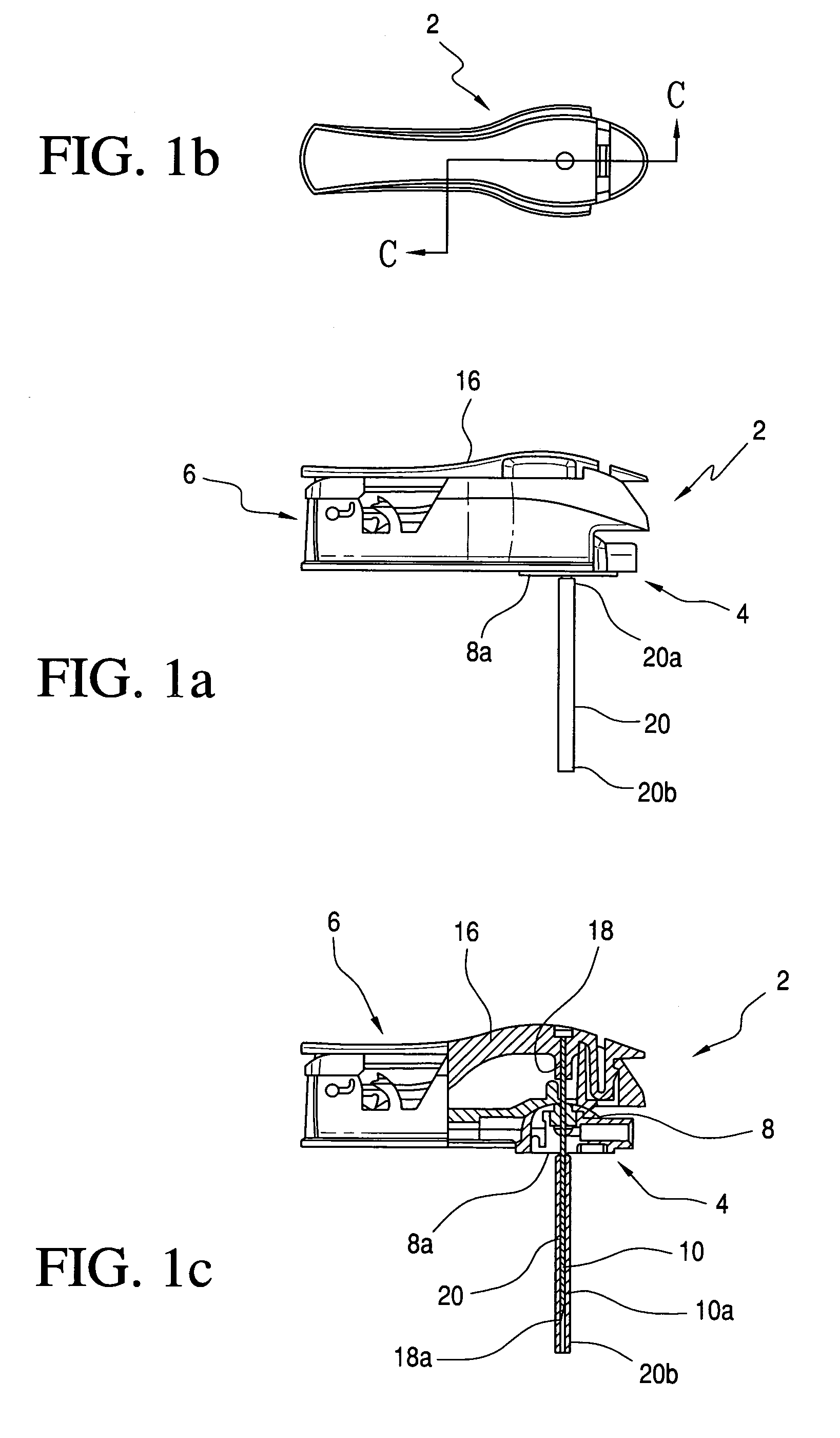
[0025]With reference to FIGS. 1A-1C, an exemplar cannula / trocar device 2 of the invention disclosed in publication 2007 / 0149921 and 2007 / 0149920 is shown. FIG. 1A shows the side view of the device, FIG. 1B shows the top view of the device and FIG. 1C shows a cross-sectional view of the device. The respective disclosures of the '921 and '920 publications are incorporated by reference herein.

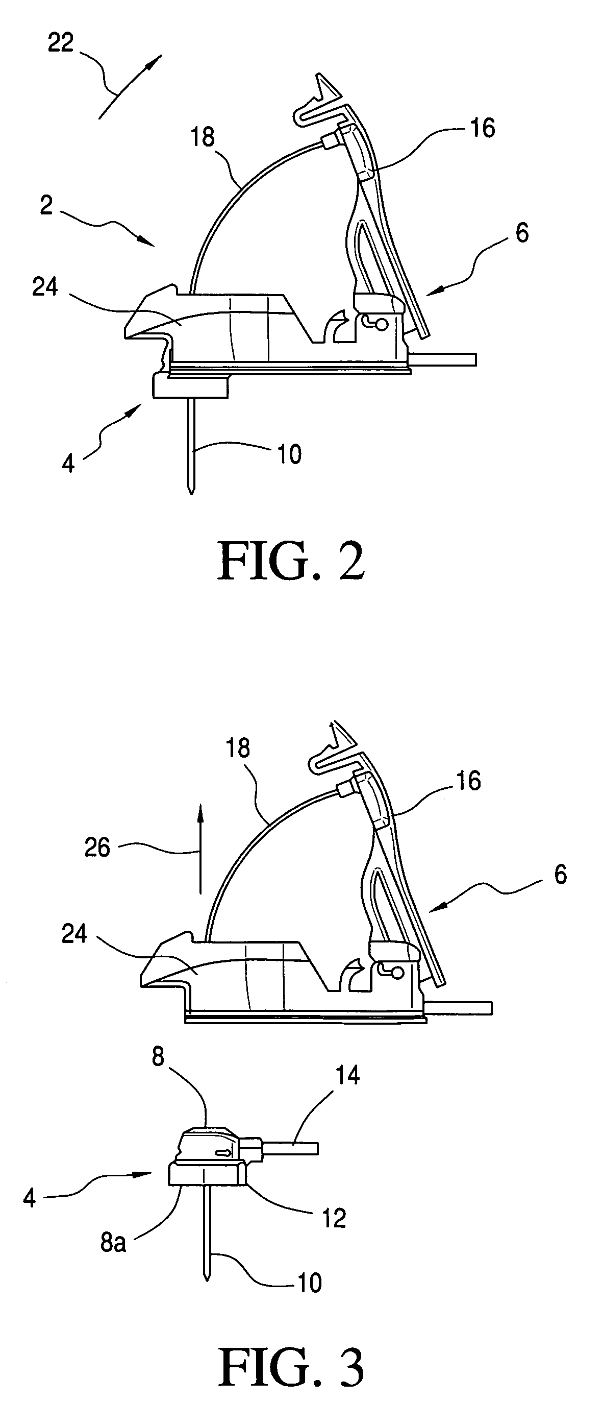
[0026]As shown, device 2 has an infuser or an infusion site 4 and an inserter or inserter assembly 6. As best shown in FIG. 1C, the infusion site has a base or a septum 8 that is fitted to a concave space in inserter assembly 6. Also with reference to FIGS. 2 and 3, a cannula 10 that may be made of stainless steel extends from the bottom surface 8a of base 8. For this discussion, bottom surface 8a is assumed to be a part of the base even though in actuality it may be the bottom surface of a foam pad 12 having an adhesive layer for making contact with the patient. A tube 14, as shown in FIG. 3, is ...


PUM


Abstract

A needle protector that protects the tip or distal end of a cannula, a trocar, or a cannula / trocar combination, is provided by an extruded tubing that has at least a section thereof that includes one or a plurality of protrusions or protuberances that are configured in a given fashion so that there is a slight bend created at that section of the tube, when the tube is fitted onto a cannula or trocar with the protrusions coming into contact with the outer diameter surface of the cannula or trocar. This results in friction contact between the protrusions and the cannula or trocar to maintain the tube protector in place relative to the cannula or trocar. The protrusions may be punched or lanced in the tube to a given depth towards the interior of the tube to establish a given friction contact.

Description

FIELD OF THE INVENTION[0001]The present invention relates to cannulas and / or trocars, and more particularly relates to a tube protector for a cannula, a trocar, and / or a cannula that has fitted thereinto a trocar.BACKGROUND OF THE INVENTION[0002]In the manufacture, distribution and use of needle products, it is important to protect the tip or distal end of the needle, cannula or trocar from damage. There are many ways to accomplish this. One typical method is to use an extruded tube cut to the appropriate length with the inside diameter (ID) of the tube sized to provide a friction fit to the outside diameter (OD) of the needle, trocar or the cannula that the tube is to protect. It is reasonable to assume a tolerance of + / −0.002 for the ID of the extruded tubing.[0003]To design a frictional fit between the tip protector and the trocar or cannula so that the tip protector does not fall off or be removed too easily from the cannula or trocar (cannula / trocar), the design of the tube pro...

Claims


Application Information

Patent Timeline
Patent Type & Authority Patents(United States)
IPC IPC(8): A61M5/178
CPCA61M5/158A61M5/3202A61M2005/1585
Inventor BELING, WILLIAMTRAVIS, RONALDFINBERG, KRISTINMARRS, JAMESPETERSON, LYLE V.CRONQUIST, RANDALL
Owner SMITHS MEDICAL ASD INC
Why Eureka
Try Eureka