Cyclone separator

a technology of cyclone separator and separator, which is applied in the direction of filtration separation, auxillary pretreatment, separation process, etc., can solve the problems of low collection efficiency, electro-pneumatic controller contamination, and electro-pneumatic controller contamination with de-icing fluid and dir

Active Publication Date: 2011-04-26
THE BOEING CO
View PDF32 Cites 26 Cited by
  • Summary
  • Abstract
  • Description
  • Claims
  • Application Information

AI Technical Summary

Problems solved by technology

A problem with EAI systems is contamination of the electro-pneumatic controller.
The electro-pneumatic controller can become contaminated with de-icing fluid and dirt.
The existing solution has very low collection efficiency, and can result in clogged liquid and debris discharge opening of the orifice, which can lead to contaminating the EAI controller components downstream of the orifice, with liquid and debris.
After some time, using the existing solution can result in EAI system failure.
Such failure may require removal cleaning and reinstallation of several EAI system components, including the drainage system.
This is time consuming and can lead to downtime of a commercial airplane resulting in loss in revenue to an airline.

Method used


Image

  • Cyclone separator
  • Cyclone separator
  • Cyclone separator

Examples


Embodiment Construction

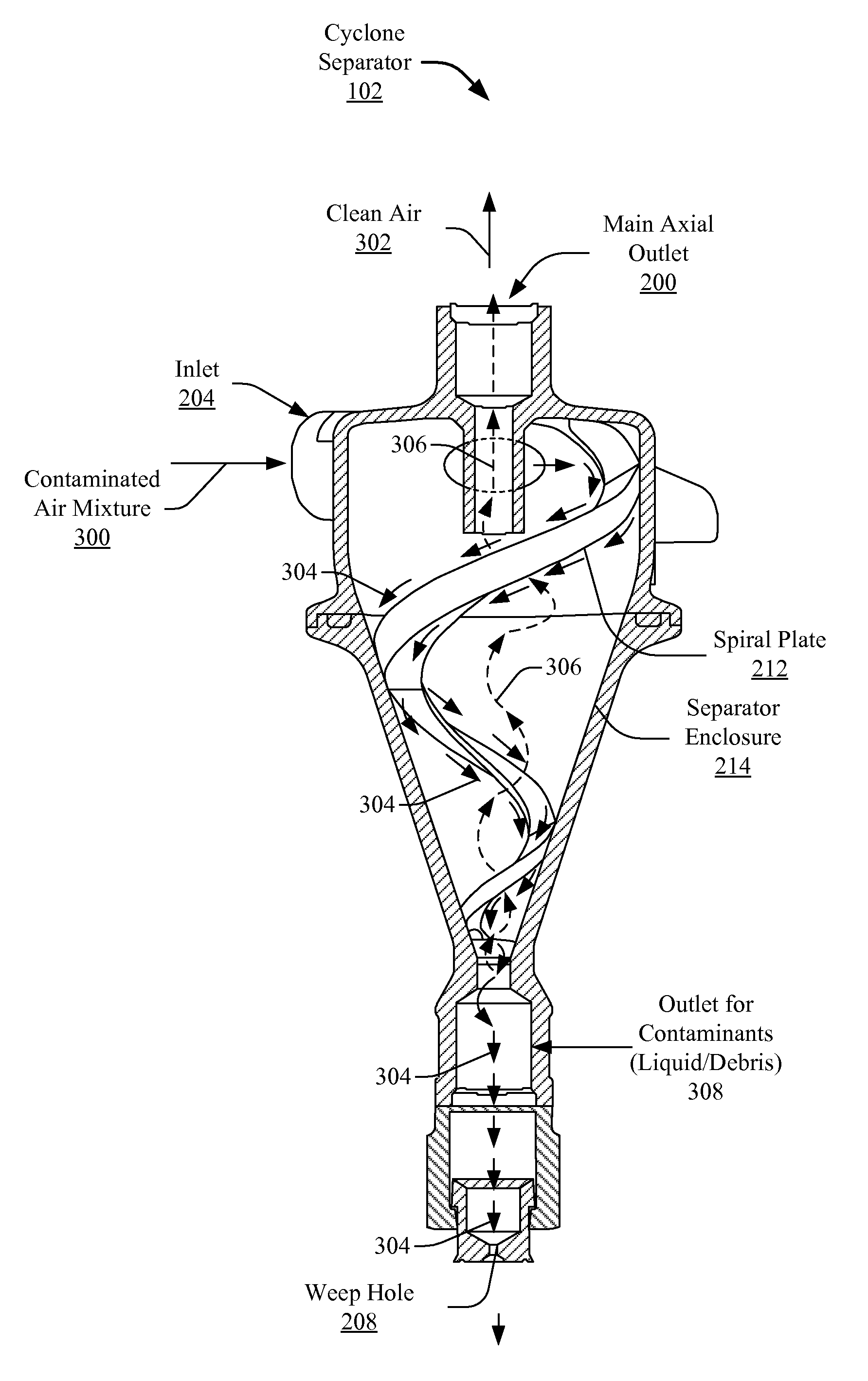
[0012]The present disclosure teaches systems and methods for a contaminant separator or cyclone collector in an Engine Anti-Ice (EAI) system. Many specific details of certain embodiments of the invention are set forth in the following description and in FIGS. 1-4 to provide a thorough understanding of such embodiments. One skilled in the art will understand that the invention may have additional embodiments, or that the invention may be practiced without several of the details described in the following description. Furthermore, although described in the context of an airplane EAI system, it is to be understood that the systems and disclosures can be applied to other systems, including automobile and pneumatic manufacturing systems.

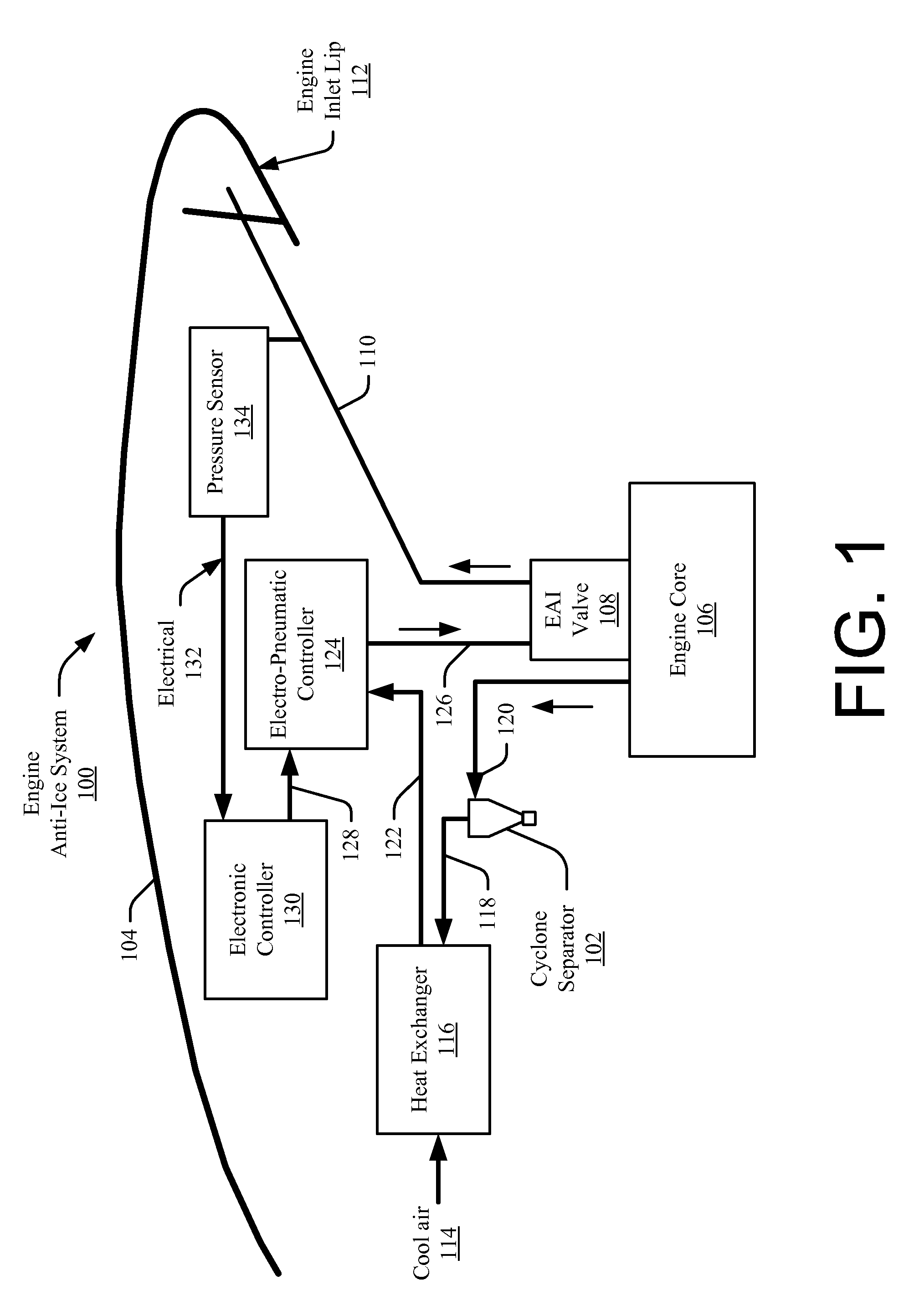
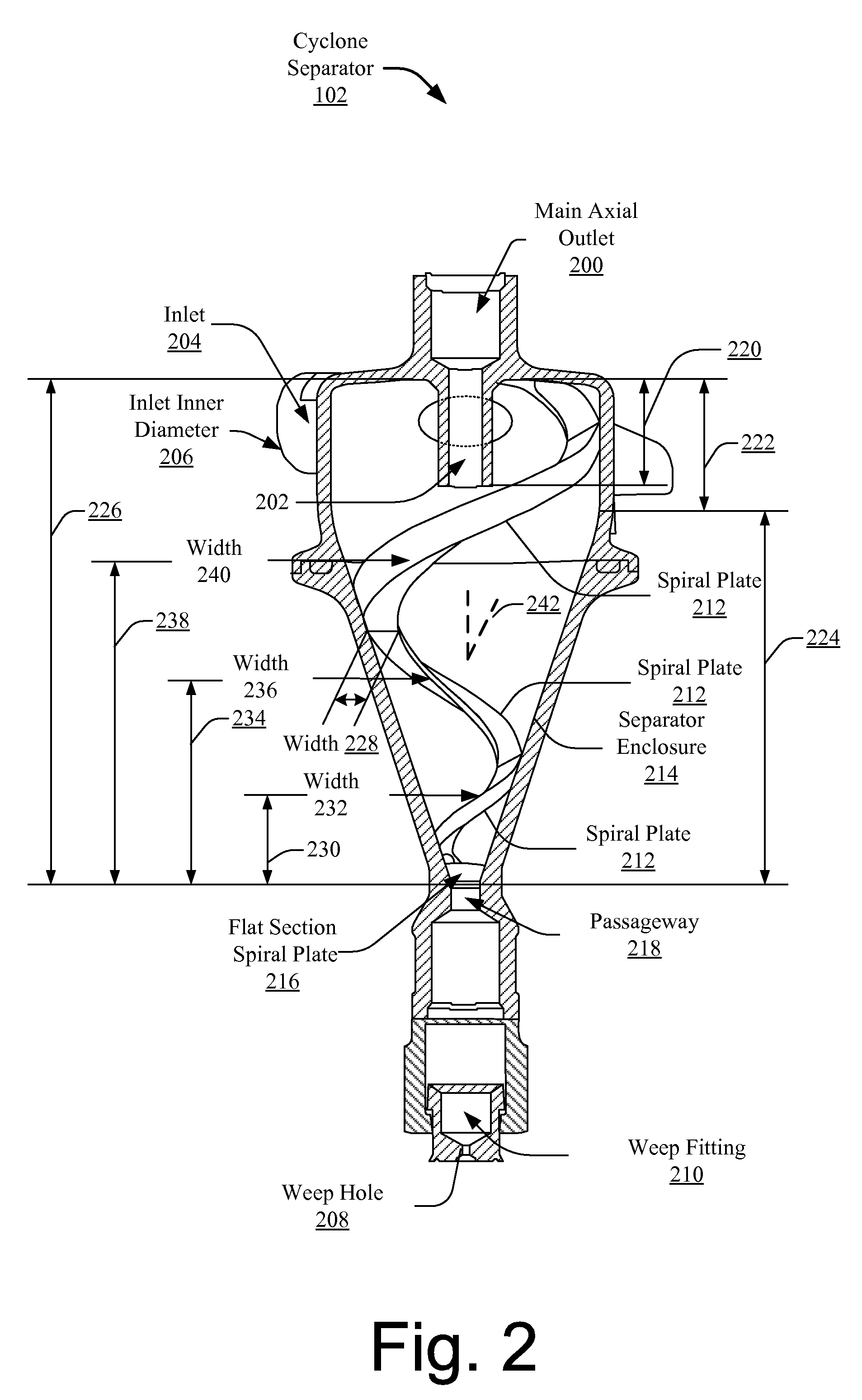
[0013]FIG. 1 illustrates an exemplary Engine Anti-Ice (EAI) system 100 that employs a contaminant separator or cyclone separator 102. The cyclone separator 102, as discussed further below, separates liquid / debris (i.e., contaminants) from a main airstream...


PUM

PropertyMeasurementUnit
angleaaaaaaaaaa
operating pressuresaaaaaaaaaa
inner diameteraaaaaaaaaa

Abstract

Systems and methods for separating contaminants in a contaminated airstream are described. In one embodiment, a contaminated airstream is received and a vortex is created that separates the contaminated airstream into a clean airstream used in the system and contaminants (e.g., debris and particles).

Description

FIELD OF THE INVENTION[0001]The field of the present disclosure is a liquid / debris contaminants separator that divides an incoming airflow mixture (e.g., air, liquid and / or debris) into two streams, a clean air stream for downstream system use, and a contaminants discharge stream.BACKGROUND OF THE INVENTION[0002]Airplanes, and particularly commercial airplanes, make use Engine Anti-Ice (EAI) systems to melt ice from their engine cowlings. In a typical EAI system, an electro-pneumatic controller controls an EAI valve and position of the EAI valve. The EAI valve in turn controls hot bleed air that is used to heat or melt ice from an engine inlet lip.[0003]A problem with EAI systems is contamination of the electro-pneumatic controller. The electro-pneumatic controller can become contaminated with de-icing fluid and dirt. Typical solutions to this problem include adding an orifice in the EAI ducting system, to drain the liquid and debris out of the EAI system. The existing solution depe...

Claims


Application Information

Patent Timeline
Patent Type & Authority Patents(United States)
IPC IPC(8): B01D45/12
CPCB01D45/16B04C5/081B04C5/103B04C11/00F02C7/047F02C7/052Y10S55/34Y02T50/671F05D2260/607F05D2260/604F05D2250/15Y02T50/675Y02T50/60
Inventor AL-ALUSI, THAMIR R.DRURY, ANTHONY D.BLUME, ERIC R.LEDZIAN, WAYNE F.
Owner THE BOEING CO
Why Eureka
Try Eureka