Transaction system

a technology of a transaction system and a transaction system, applied in the field of transactions systems, can solve the problems of unproductive time for a service provider, customer unprepared to start a transaction, and a long time when the service provider is not working productively, so as to improve service, facilitate installation and service, and reduce unproductive time

Inactive Publication Date: 2011-04-26
DIEBOLD NIXDORF
View PDF38 Cites 16 Cited by
  • Summary
  • Abstract
  • Description
  • Claims
  • Application Information

AI Technical Summary

Benefits of technology

[0027]Although the customer conducting transactions at the customer station will still engage in activities which in other environments would result in unproductive time for the service provider, the service provider is enabled to switch to communication with other customer stations to move other transactions forward while waiting for the customer. The ability of the service provider to minimize unproductive time while waiting for the customer improves service for all customers using the system. The queuing display at the service p...

Problems solved by technology

Studies have shown that in this type of service environment there is often considerable time when the service provider is not working productively.
One factor is that a customer is not ready to start a transaction when they reach the front of the line at the counter or window.
Another example of unproductive time for a service provider is encountered in situations where the service provider is required to wait for equipment to operate.
While computerized systems are often used for this purpose, there is still a time lag.
After the authorization is obtained, the teller often encounters another delay while a counting machine counts out the money for the customer.
Once the credit card is authorized, there is often further delay while printing equipment prints the customer's tickets.
A further cause of unproductive time in transaction environments is the time taken by customers to verify what has been provided to them.
However, while the customer performs these activities t...

Method used


Image

  • Transaction system
  • Transaction system
  • Transaction system

Examples


Embodiment Construction

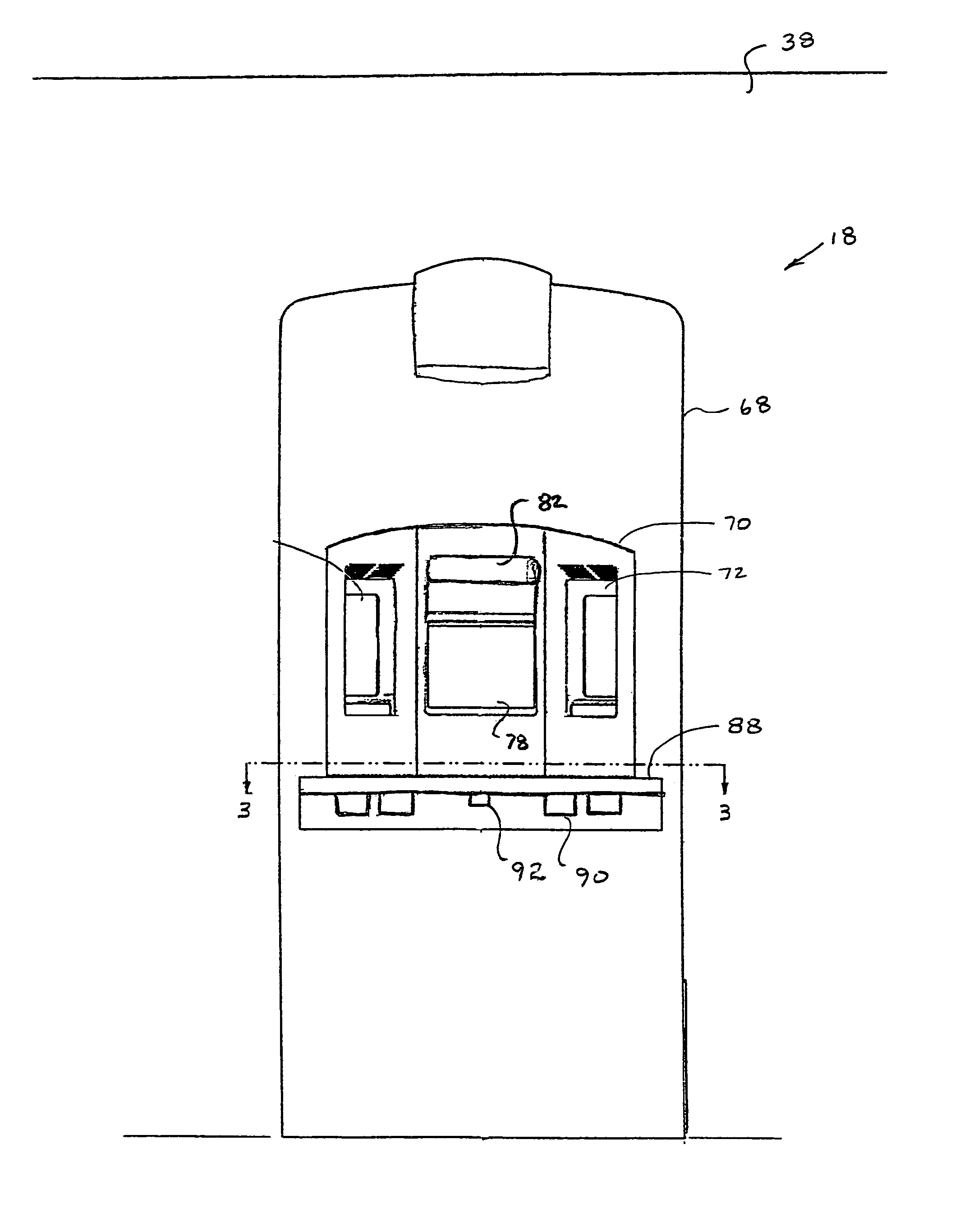
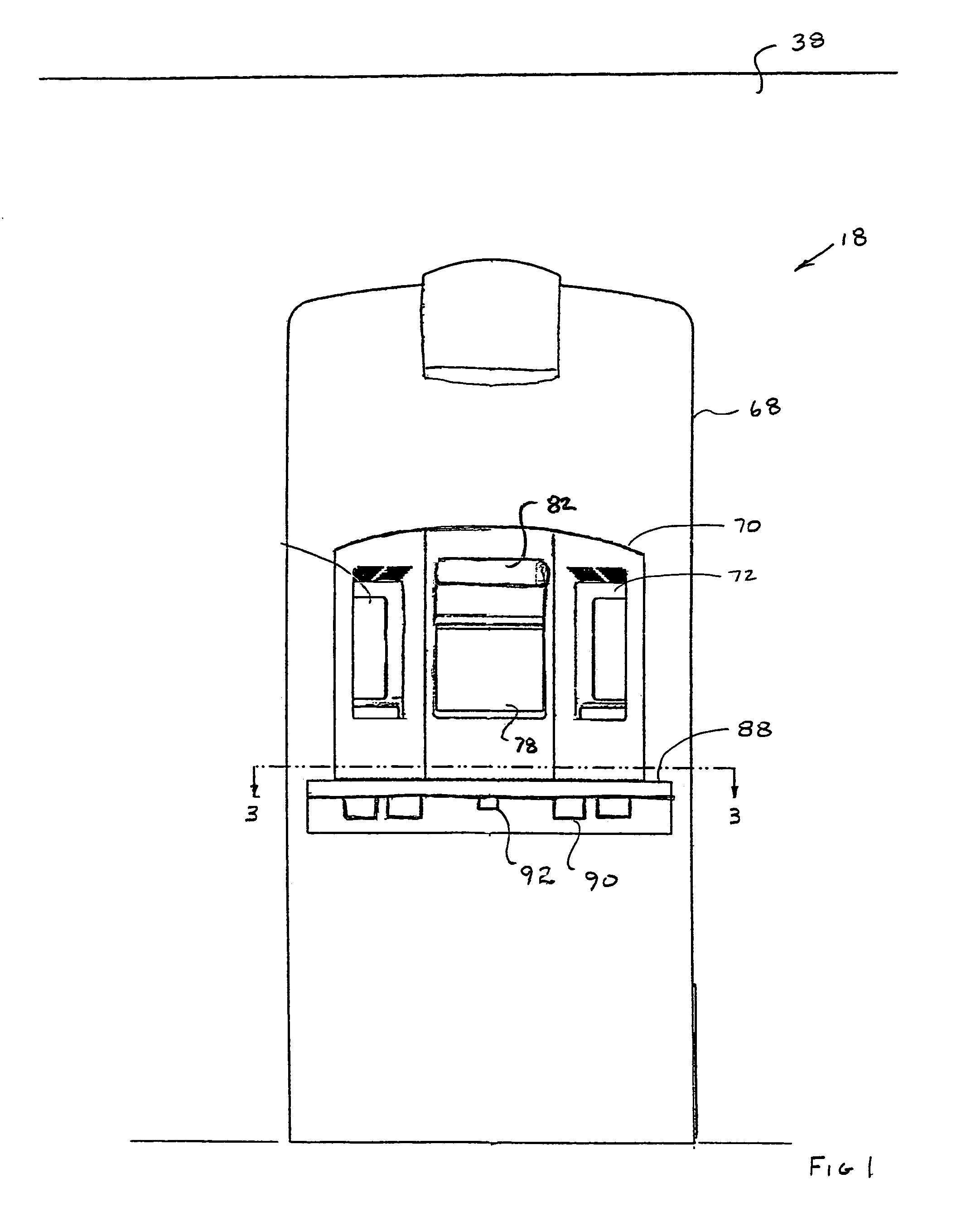
[0041]Referring now to the drawings and particularly to FIG. 10 there is shown therein an embodiment of the transaction system of the present invention generally indicated 10. The system is used within a building or facility generally indicated 12, in which transactions are conducted. The embodiment of the system shown is specifically adapted for conducting banking type transactions. It should be understood however that the present invention may be used in a variety of transaction environments including gaming, ticketing, pharmacy, postal and other business environments where customers are served by a service provider positioned behind a desk, counter or window.

[0042]The system of the present invention includes a service provider (SP) station generally indicated 14. A service provider generally indicated 16 operates the components and equipment at the SP station. In the case of the embodiment of the system shown, the service provider is a teller or other bank employee that carries o...


PUM


Abstract

A system for carrying out transactions (10) includes customer stations (18) and a service provider station (14). The system is operated in a building (12) or other facility in which a service provider operates the service provider station in a secure room (36). Audio and video communications are established between customers at the customer stations and the service provider at the service provider station. Items are exchanged between customers and the service provider through carriers (26) transmitted through a pneumatic tube system (22). A video material presentation device (50) provides promotional or other video material which is presented on displays at the customer stations. Video material is presented to customers when the customer terminal is not in communication with the service provider terminal. The customer stations are readily installed and configured in the transaction facility to maximize the floor space available for other purposes.

Description

[0001]This application claims the benefit of U.S. Provisional Application(s) No. 60 / 045,794 filing date May 7, 1997.TECHNICAL FIELD[0002]This invention relates to equipment and systems used for carrying out transactions. Specifically, this invention relates to a system for carrying out transactions between customers and a service provider, which transactions may relate to banking, gaming, ticketing, bill paying, pharmacy, postal or other services.BACKGROUND ART[0003]For hundreds of years many types of commercial transactions have been carried out the same way. Customers stand in line to be serviced by an individual who acts as a service provider. The service provider is positioned behind a window, desk or counter. Common examples of situations in which customers are served using this approach are in banking, gaming, post offices, pharmacies, and ticketing for movie theaters and sporting events.[0004]Studies have shown that in this type of service environment there is often considera...

Claims


Application Information

Patent Timeline
IPC IPC(8): H04N9/47G07B1/00B65G51/06B65G61/00B66B9/04G06Q20/00G06Q50/00G07B5/00G07D9/00G07F19/00H04N7/18
CPCG07F19/20H04N7/18G07F19/201
Inventor FRAZZITTA, BARTHOLOMEW J.BENORE, RANDOLPH C.MCINTYRE, DANIEL S.DEPIETRO, MARK AKALMAN, JEFFREY M
Owner DIEBOLD NIXDORF
Why Eureka
Try Eureka