Sound reproducing apparatus and method of identifying positions of speakers

a technology of sound reproduction and positioning position, which is applied in the direction of stereophonic arrangments, gain control, instruments, etc., can solve the problems of inability to obtain the angle of each speaker with respect to an optimal listening position, inability to detect inappropriate speaker layout, and out of place sound image localization

Inactive Publication Date: 2011-04-26
YAMAHA CORP
View PDF14 Cites 142 Cited by
  • Summary
  • Abstract
  • Description
  • Claims
  • Application Information

AI Technical Summary

Problems solved by technology

It is therefore likely that sound image localization will be out of place if the layout of the speakers is greatly different from the recommended layout.
According to the sound image localization adjusting apparatus in Patent Document 1, it is therefore impossible to obtain an angle of each speaker with respect to an optimal listening position.
Even if this angle is greatly different from that in a recommended position, the inappropriate layout of the speakers cannot be detected.
Thus, there is a problem that only an in adequate sound image localization correction process can be performed.

Method used


Image

  • Sound reproducing apparatus and method of identifying positions of speakers
  • Sound reproducing apparatus and method of identifying positions of speakers
  • Sound reproducing apparatus and method of identifying positions of speakers

Examples


first embodiment

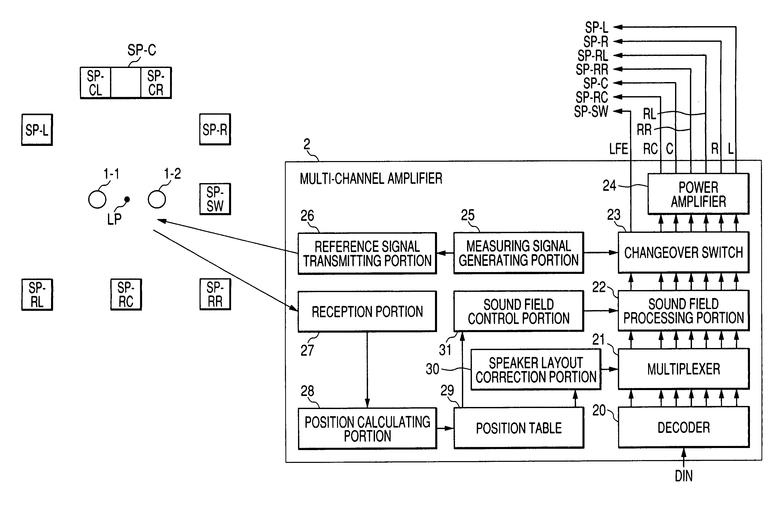
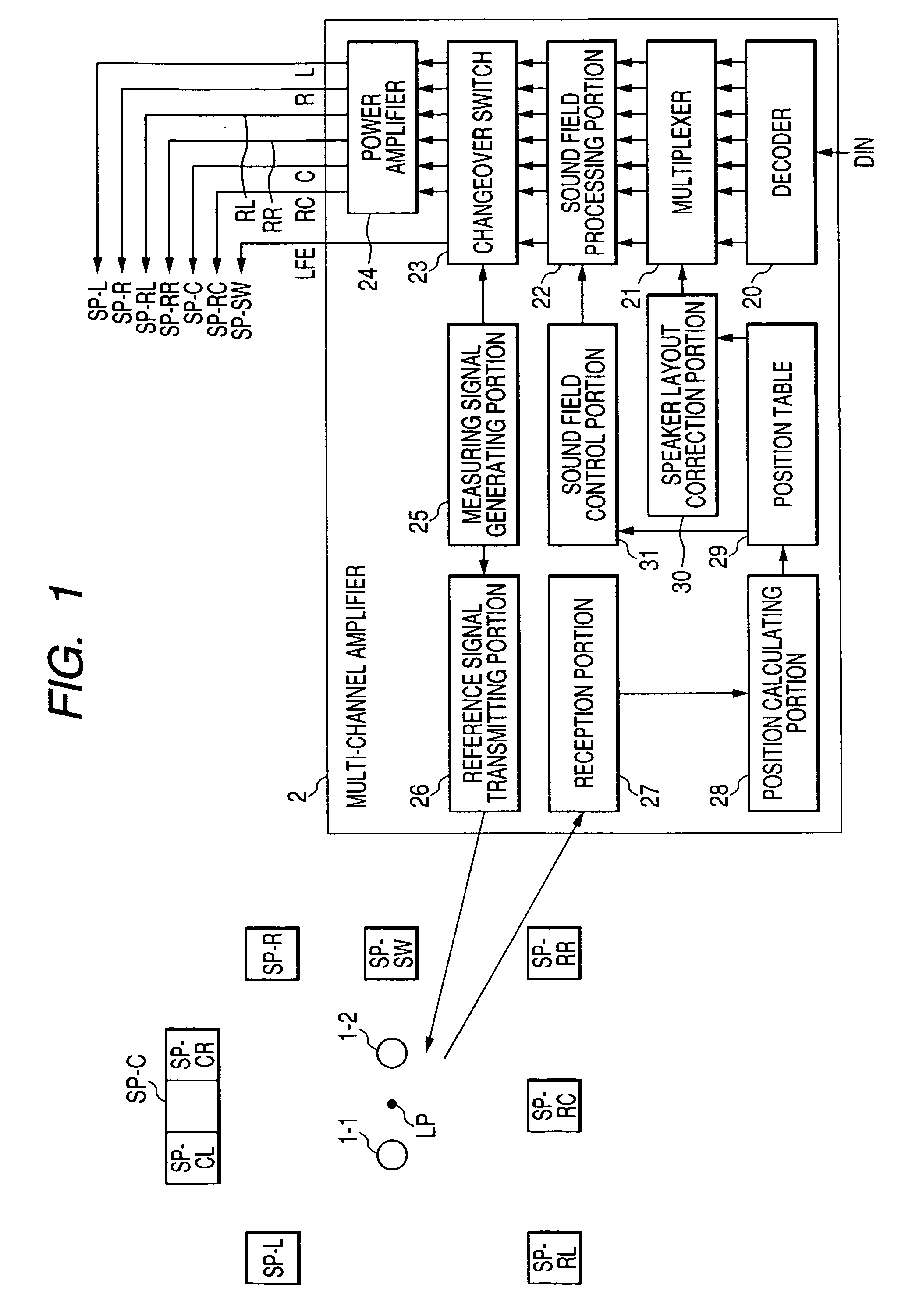
[0049]Embodiments of the present invention will be described below in detail with reference to the drawings. FIG. 1 is a block diagram showing the configuration of a sound reproducing apparatus according to a first embodiment of the present invention.

[0050]The sound reproducing apparatus in FIG. 1 includes sensors 1 (1-1 and 1-2) for detecting positions of speakers SP-C, SP-L, SP-R, SP-RL, SP-RR, SP-RC and SP-SW, and a multi-channel amplifier 2.

[0051]The multi-channel amplifier 2 includes a decoder 20, a multiplexer 21, a sound field processing portion 22, a changeover switch 23, a power amplifier 24, a measuring signal generating portion 25, a reference signal transmitting portion 26, a reception portion 27, a position calculating portion 28, a position table 29, a speaker layout correction portion 30 and a sound field control portion 31.

[0052]The measuring signal generating portion 25 constitutes a generation means. The reference signal transmitting portion 26 constitutes a transm...

second embodiment

[0077]Next, description will be made on a second embodiment of the present invention. This embodiment is to explain operation in the case where the listening position LP is changed for some reason after the position of each speaker is detected in the first embodiment. Therefore, the configuration as the sound reproducing apparatus is the same as that in FIG. 1. Description will be made using the reference numerals in FIG. 1. FIG. 5 is a flow chart showing a process when the listening position LP is changed.

[0078]First, a listener installs the sensor 1-1 in a changed listening position LP′ as shown in FIG. 6. In this event, the sensor 1-2 may not have to be installed.

[0079]The measuring signal generating portion 25 of the multi-channel amplifier 2 generates a measuring signal for detecting a speaker position (Step 201 in FIG. 5). In this event, assume that the changeover switch 23 supplies the measuring signal to the center speaker SP-C, but does not supply the signal to the other sp...

third embodiment

[0089]Next, description will be made on a third embodiment of the present invention. FIG. 7 is a block diagram showing the configuration of a sound reproducing apparatus according to the third embodiment of the present invention. Constituents the same as those in FIG. 1 are referenced correspondingly. The sound reproducing apparatus in FIG. 7 includes sensors 1a (1a-1 and 1a-2) and a multi-channel amplifier 2a.

[0090]Although a time difference for calculating a distance between a speaker and a sensor is measured by the sensor 1 in the first embodiment, a time difference measuring portion 32 for measuring a time difference is provided in the multi-channel amplifier 2a in this embodiment.

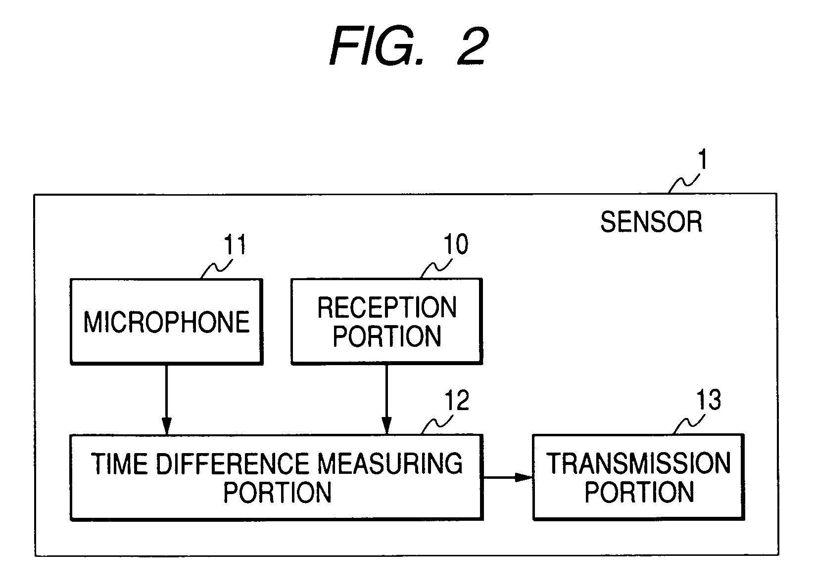
[0091]FIG. 8 is a block diagram showing the configuration of each sensor 1a (1a-1, 1a-2). The sensor 1a has a microphone 11 and a transmission portion 13a.

[0092]FIG. 9 is a flow chart showing a sound field correction process according to this embodiment. In the same manner as in the first embodiment,...


PUM


Abstract

A position of a speaker is detected two-dimensionally or three-dimensionally, and a sound field is corrected. A sound reproducing apparatus includes a measuring signal generating portion for generating a first measuring signal, a transmission portion for transmitting a second measuring signal as soon as the first measuring signal is generated, sensors disposed in a listening position and for measuring a time difference between a time instant when the second measuring signal was received and a time instant when a measuring sound wave radiated from a to-be-detected speaker in accordance with the first measuring signal was received, and a position calculating portion for calculating a distance, as to each of n sensors, between each of the n sensors and the to-be-detected speaker based on the measured time difference, and calculating the position of the to-be-detected speaker based on distances among the n sensors and the calculated distance.

Description

[0001]This is a U.S. National Phase Application of PCT International Application PCT / JP2005 / 002833 filed on Feb. 16, 2005.TECHNICAL FIELD[0002]The present invention relates to a sound reproducing apparatus for reproducing multi-channel sound, and particularly, relates to a sound reproducing apparatus and a method of identifying positions of speakers in which positions of speakers are detected two-dimensionally or three dimensionally so that a sound field can be corrected effectively.TECHNICAL BACKGROUND[0003]Recently, multi-channel audio signals such as 5.1-channel audio signals are recorded in some audio sources such as DVDs. Multi-channel sound reproducing systems for reproducing such audio sources have been coming into wide use even in general homes. In such a multi-channel sound reproducing system, a multi-channel sound reproducing effect expected by an audio equipment maker can be obtained when respective speakers are disposed in a listening room according to a layout method re...

Claims


Application Information

Patent Timeline
Patent Type & Authority Patents(United States)
IPC IPC(8): H04R29/00H04S5/02G10K15/00H04R5/02H04S7/00
CPCH04R5/02H04S7/308H04S7/301H04R2205/024
Inventor MORISHIMA, MORITO
Owner YAMAHA CORP
Why Eureka
Try Eureka