Welding helmet having an automatic lighting system

a technology of automatic lighting and welding helmets, applied in the field of welding helmets, can solve problems such as not being suitable for the purpos

Inactive Publication Date: 2011-05-03
SCHWANZ KENNETH H
View PDF7 Cites 54 Cited by
  • Summary
  • Abstract
  • Description
  • Claims
  • Application Information

AI Technical Summary

Benefits of technology

[0012]AN OBJECT of the present invention is to provide a welding helmet having an automatic lighting system that avoids the disadvantages of the prior art.

Problems solved by technology

Furthermore, even though these innovations may be suitable for the specific individual purposes to which they address, accordingly, they would not be suitable for the purposes of the present invention as heretofore described.

Method used


Image

  • Welding helmet having an automatic lighting system
  • Welding helmet having an automatic lighting system
  • Welding helmet having an automatic lighting system

Examples


Embodiment Construction

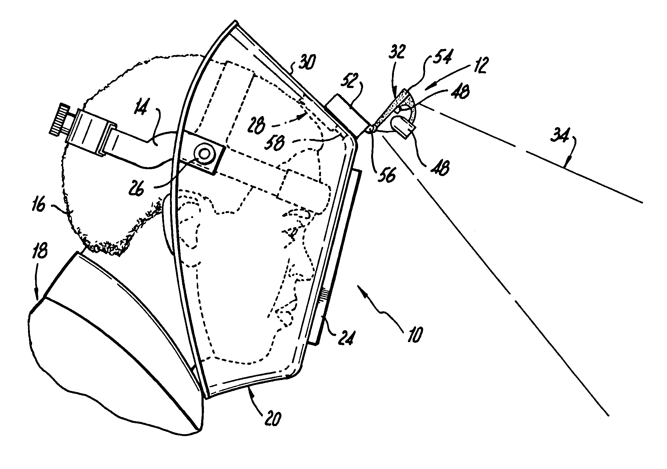
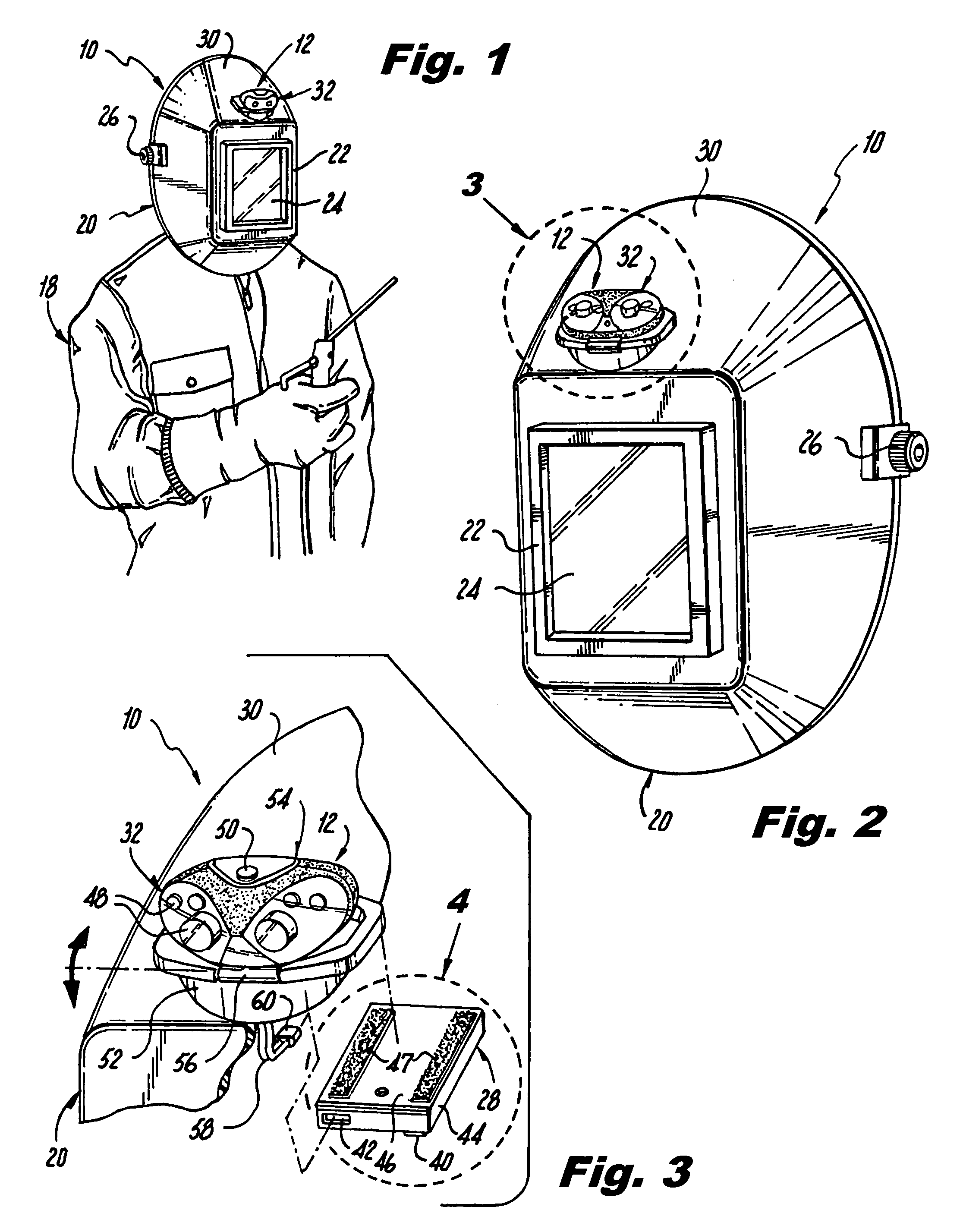
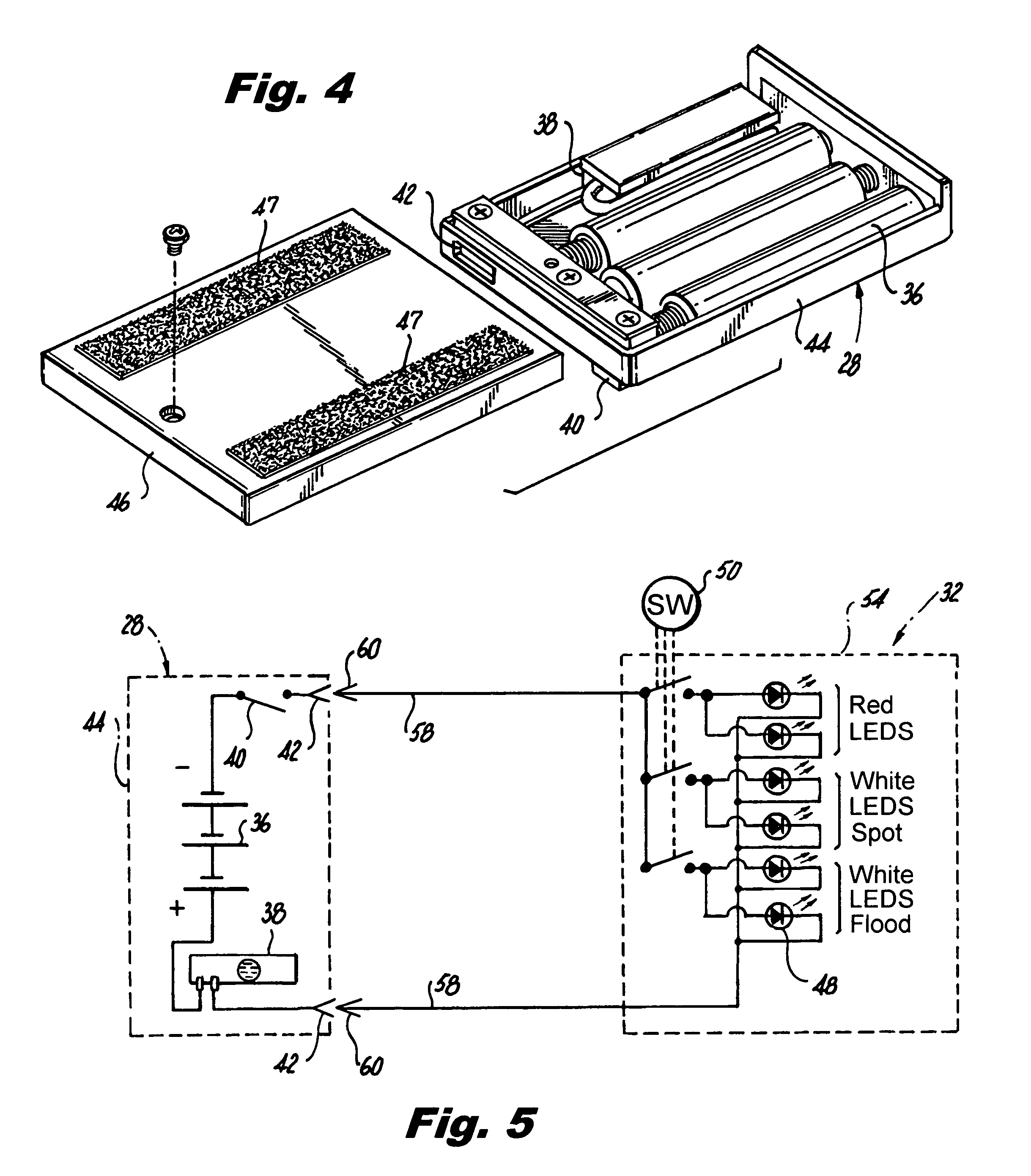
[0053]Referring now to the figures, in which like numerals indicate like parts, and particularly to FIGS. 1 through 7, which are a diagrammatic perspective view of an embodiment of the present invention worn by a welder; an enlarged diagrammatic perspective view of the present invention per se; a further enlarged perspective view, showing in greater detail the automatic lighting system taken in the area enclosed in the dotted circle indicated by arrow 3 in FIG. 2; a still further enlarged diagrammatic perspective view, with parts broken away, taken of the area enclosed in the dotted curve indicated by arrow 4 in FIG. 3, with the cover exploded showing the batteries, gravity sensitive tilt switch and associated components therein; a schematic diagram of the electrical circuit of the automatic lighting system; a diagrammatic side view taken in the direction of arrow 6 in FIG. 1, showing the face shield of the welding helmet of the present invention raised up in a non-shielding positio...


PUM


Abstract

A welding helmet having a headband that fits upon a head of a welder, and a face shield with a viewing port having a light filtering window that pivots on the headband between a raised up non-shielding position and a lower down shielding position has an automatic lighting system with a power source component secured to a interior bottom surface of a top portion of the face shield, and an illumination component secured to a top exterior surface of the top portion of the face shield for lighting a work area outside the helmet. The energizing of the lighting system is responsive to the position of the raising and lowering of the face shield of the helmet so as to permit the welder to better perceive his/her surroundings.

Description

BACKGROUND OF THE INVENTION[0001]1. Field of the Invention[0002]The present invention relates to a welding helmet, and more particularly, a welding helmet having an automatic lighting system.[0003]2. Description of the Prior Art[0004]Numerous innovations for helmets having lighting devices have been provided in the prior art that will be described. Even though these innovations may be suitable for the specific individual purposes to which they address, however, they differ from the present invention.[0005]A FIRST EXAMPLE, U.S. Pat. Office Document No. 4,332,004, Issued on May 25, 1982, to Slaughter teaches a lighting system for a welders helmet which includes a high intensity, high Kelvin temperature electric light source attached to the face shield for directing a high energy, high Kelvin temperature light beam forwardly of the viewing port, and an energizing circuit including an on-off switch interconnecting the light source to a source of electrical energy which de-energizes the ...

Claims


Application Information

Patent Timeline
Patent Type & Authority Patents(United States)
IPC IPC(8): F21V21/084
CPCF21L4/04F21V23/0442F21V33/00F21V21/14F21V21/084F21Y2101/02F21Y2115/10F21V23/0492A61F9/06
Inventor SCHWANZ, KENNETH H.
Owner SCHWANZ KENNETH H
Why Eureka
Try Eureka