Al technical title is built by PatSnap Al team. It summarizes the technical point description of the patent document.
a guide catheter and sheath technology, applied in the direction of catheters, prostheses, therapy, etc., can solve the problems of difficult, if not impossible, to advance the guide wire all the way to the ultimate target site, and achieve a balan
Inactive Publication Date: 2011-05-03
CARDIOFOCUS INC
View PDF224 Cites 124 Cited by
Summary
Abstract
Description
Claims
Application Information
AI Technical Summary
This helps you quickly interpret patents by identifying the three key elements:
Problems solved by technology
Method used
Benefits of technology
[0016]In one aspect, the deflectable sheath catheters include a deflectable tip section at a distal end and having a varying stiffness along at least a portion of the distal tip section which allows the deflectable tip to deflect along a compound curve. As a result of this tip, the present invention permits ready access to all four pulmonary veins of the left atrium via a single transseptal approach, especially the right inferior pulmonary vein. Moreover, this access is achieved without prolapsing and in a manner that also permits the application of axial force, such that an ablation instrument inserted through the sheath catheter can be both maneuvered into place and held in position during ablation. This is especially useful when the ablation instrument includes a balloon element that must be urged against the ostium of a vein in order to occlude it.
[0041]In another aspect of the invention, a cardiac ablation instrument assembly is disclosed having a deflectable sheath catheter adapted for disposition within a heart and at least one ablation instrument which can be deployed via a proximal hemostasis valve and through the deflectable sheath catheter to a desired target location. A deflectable sheath catheter is provided (and, optionally a dilator as previously described above) having a handle at a proximal end and a deflectable tip section at a distal end. The deflectable tip section provides access to the heart and target region of cardiac tissue and allows an ablation instrument to reach the target cardiac tissue, preferably in the left atrium of the heart to access the pulmonary veins for the treatment of atrial fibrillation. The sheath is able to “point” the ablation device at the ostium of the pulmonary vein and the ablation instrument is advanced to the target tissue and axial force can be applied to maintain contact with the target tissue during ablation of the tissue.
Problems solved by technology
By ablating the heart tissue at these locations, the electrical conductivity from one segment to another can be blocked such that the resulting segments become too small to sustain the fibrillatory process on their own.
However, one drawback associated with this method, when the target ablation sites are in or near the pulmonary veins on the posterior surface of the heart, is that it is often difficult, if not impossible, to advance the guide wire all the way to the ultimate target site due to the shape of the heart muscle.
However, achieving a balance between the “pushability” of the catheter (that is, the ability to direct the tip of the catheter to the target location without buckling or kinking) and the necessary stiffness to allow the catheter to access the heart, especially when navigating the sharp turns necessary to access locations in the left atrium of the heart, can be difficult.
As a result, these catheters often require large spatial volumes in which to bend and are unable to make tight turns that are sometimes necessary to reach a target region without causing trauma to a patient.
Particularly, access to the left atrium for the treatment of atrial fibrillation is particularly difficult when the ultimate target region is in the vicinity of the right inferior pulmonary vein, as this vein is usually the closest to the transseptal puncture, requiring the catheter to turn 180° in direction in order to achieve proper orientation.
Currently methods to address this issue include using a set of sheath catheters with different curves and removing one catheter and replacing it with another, several times. However, this exchange is time consuming and can present additional risks, such as accidental entrainment of air embolisms.
More difficulties arise when the catheter includes an ablation instrument having a balloon, as additional maneuvering can be required to properly orient the balloon within or at the mouth of the vein.
Further, axial force may be required in order to occlude the pulmonary vein at the ostium and the lack of stiffness of most catheters renders the application of sufficient force to successfully seal the vein prior to ablation problematic.
Method used
Image
Click on the blue label to locate the original text in one second.
Reading with bidirectional positioning of images and text.
Examples
Embodiment Construction
[0083]Certain exemplary embodiments will now be described to provide an overall understanding of the principles of the structure, function, manufacture, and use of the methods and devices disclosed herein. One or more examples of these embodiments are illustrated in the accompanying drawings. Those skilled in the art will understand that the methods and devices specifically described herein and illustrated in the accompanying drawings are non-limiting exemplary embodiments and that the scope of the present invention is defined solely by the claims. The features illustrated or described in connection with one exemplary embodiment may be combined with the features of other embodiments. Such modifications and variations are intended to be included within the scope of the present invention.
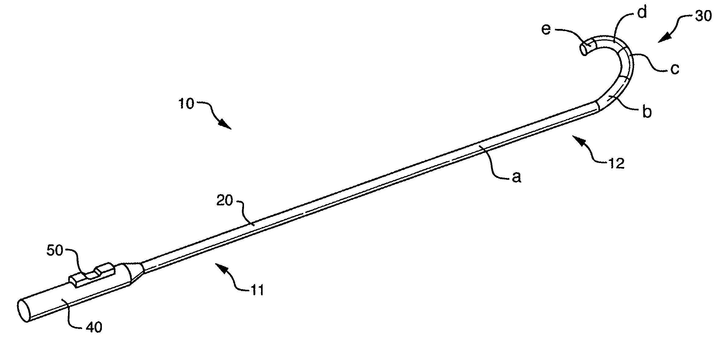
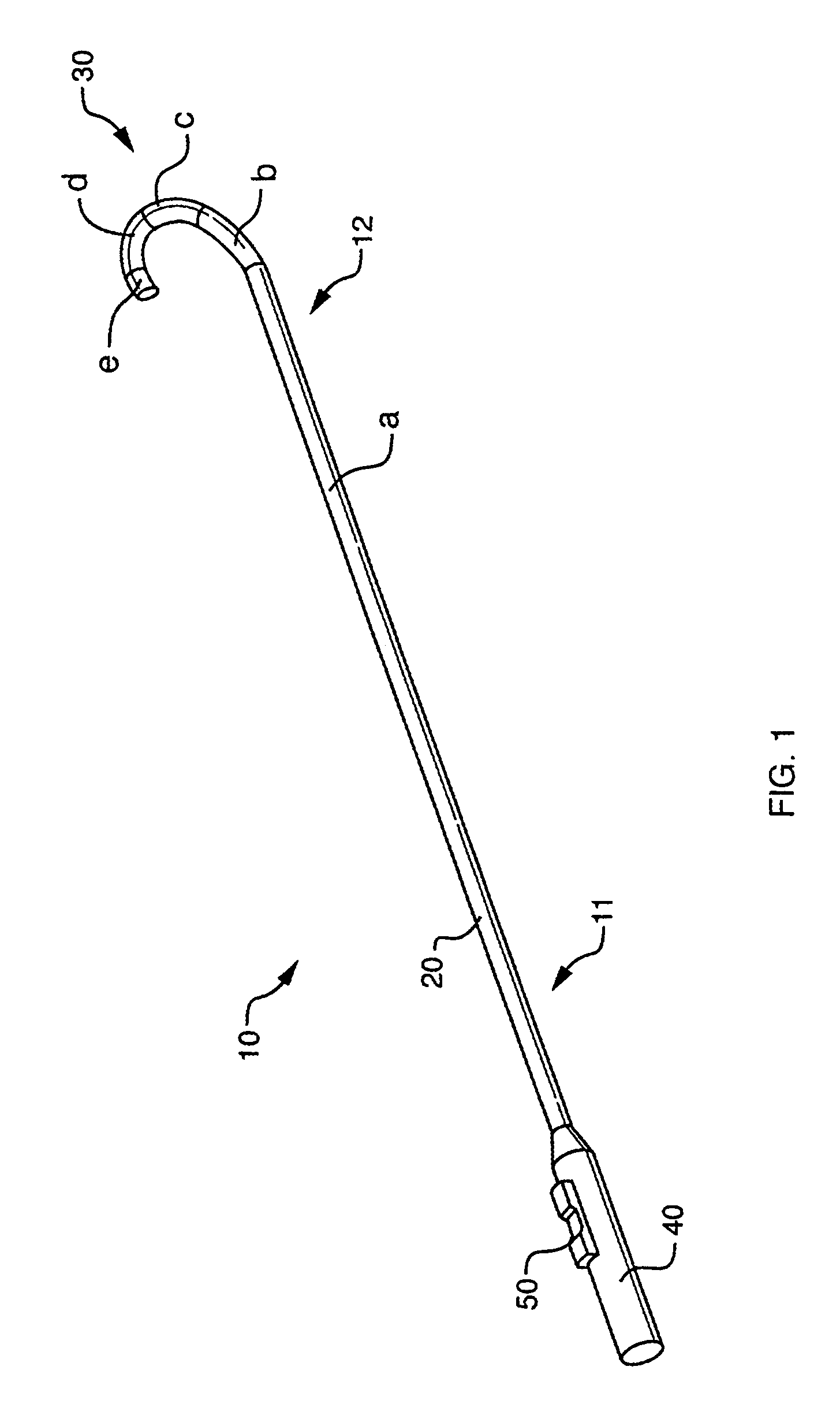
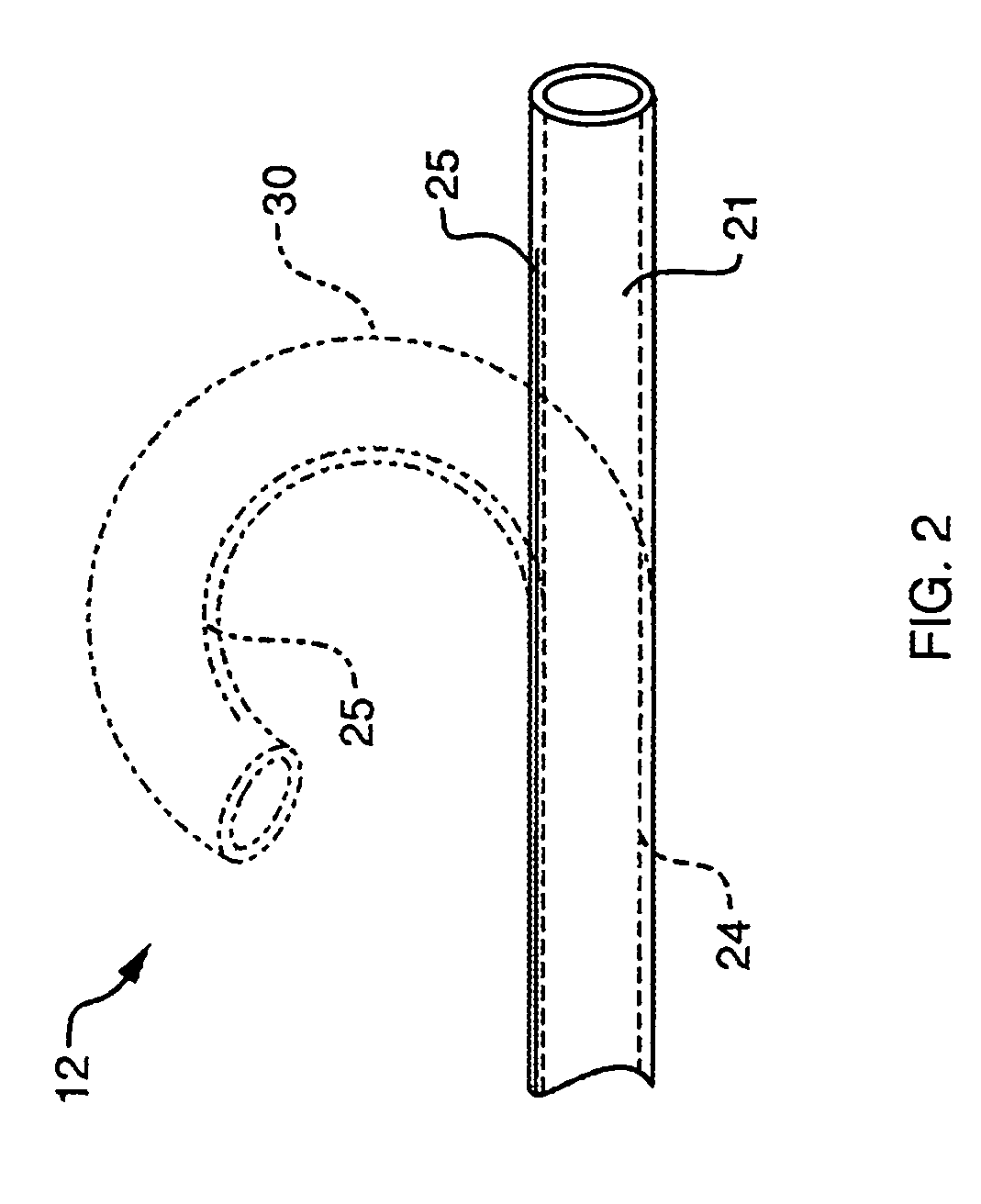
[0084]The present invention provides devices and methods for the treatment of atrial fibrillation. In one embodiment a deflectable sheath catheter includes an elongate catheter body having proximal an...
PUM
Property
Measurement
Unit
angle
aaaaa
aaaaa
angle
aaaaa
aaaaa
angle
aaaaa
aaaaa
Abstract
The present invention provides devices and methods for the treatment of atrial fibrillation. In one embodiment a deflectable sheath catheter includes an elongate catheter body having proximal and distal ends, the distal end having a distal tip region that includes a plurality of flexible segments with varying degrees of stiffness. A handle portion can be located at the proximal end of the catheter body to provide a steering mechanism that causes the distal tip region to deflect according to a compound curve.
Description
CROSS-REFERENCE TO RELATED APPLICATIONS[0001]The pending application is a continuation-in-part of U.S. patent application Ser. No. 10 / 357,156, filed Feb. 3, 2003, which is a continuation-in-part of U.S. patent application Ser. No. 09 / 924,393, filed Aug. 7, 2001.[0002]The application is also a continuation-in-part of U.S. patent application Ser. No. 10 / 674,114, filed Sep. 29, 2003, which is a continuation of U.S. patent application Ser. No. 09 / 616,275, filed Jul. 14, 2000, now U.S. Pat. No. 6,626,900 (issued Sep. 30, 2003), which is a continuation-in-part of U.S. patent application Ser. No. 09 / 602,420, filed Jun. 23, 2000, now U.S. Pat. No. 6,572,609 (issued Jun. 3, 2003), which is a continuation-in-part of U.S. patent application Ser. No. 09 / 357,355, filed Jul. 14, 1999, now U.S. Pat. No. 6,423,055 (issued Jul. 22, 2002).[0003]The pending application is also a continuation-in-part of U.S. patent application Ser. No. 10 / 865,558, filed Jun. 10, 2004, which claims priority to U.S. Prov...
Claims
Application Information
Patent Timeline
Application Date:The date an application was filed.
Publication Date:The date a patent or application was officially published.
First Publication Date:The earliest publication date of a patent with the same application number.
Issue Date:Publication date of the patent grant document.
PCT Entry Date:The Entry date of PCT National Phase.
Estimated Expiry Date:The statutory expiry date of a patent right according to the Patent Law, and it is the longest term of protection that the patent right can achieve without the termination of the patent right due to other reasons(Term extension factor has been taken into account ).
Invalid Date:Actual expiry date is based on effective date or publication date of legal transaction data of invalid patent.