Drain cleaning apparatus with restricted reverse function

a technology of reverse function and drain cleaning, which is applied in the direction of cleaning process and apparatus, rotary device cleaning, cleaning heat-transfer devices, etc., can solve the problems of deterioration and destruction of the device, the elongation or retracting of the snake, and the overload of the torque applied to the various parts of the device, so as to reduce the deterioration and damage of the mechanical components, facilitate the transportation and movement of the device, and reduce the effect of deterioration and damag

Inactive Publication Date: 2011-05-03
GEN WIRE SPRING
View PDF17 Cites 27 Cited by
  • Summary
  • Abstract
  • Description
  • Claims
  • Application Information

AI Technical Summary

Benefits of technology

[0018]It is another object of the present invention to reduce deterioration and damage to the motor, drum and snake used in the portable drum augers.
[0019]It is another object of the present invention to reduce deterioration and damage to mechanical components working in conjunction with the motor, drum and snake used in portable drum augers.
[0020]It is another object of the present invention to allow the operator to be free to perform other functions of the machine and / or other actions relating to its operation when the rotational control is the forward direction.
[0021]In accordance with one aspect of the invention, generally stated, a drum auger includes a frame. Such frame may have wheels attached to its base to facilitate easy transportation and movement of the device. The frame may also have plastic caps placed on its legs to provide greater friction with the ground.

Problems solved by technology

This force may also cause the snake to elongate or retract from the drum or housing wherein it is encased when a feed mechanism is incorporated with the machine.
In such situations an overload of torque may be applied to various parts of the devices including but not limited to the motor, drum and snake.
This can result in the deterioration and destruction of these mechanisms as well as other parts of the machine.
This thereby reduces the likelihood of the device tipping, opposite rotation of the drum occurring and / or breakage of the snake.
While such devices have improved the durability of the machine and increased safety, they do not have alternative limiting mechanisms that are directed to the direction of rotation of the drum and snake.
The prior art teaches many torque limiting mechanical devices that also deteriorate with increased use.
For example a clutch that properly performs its function will typically slip after substantial use because of natural wear and tear on the parts of the clutch performing its proper function.
Although this helps in machines that have interchangeable motors, drums and snakes that can handle different levels of torque without damage to the device, it also allows for the torque level to be incorrectly adjusted and therein negate the desired effect of the mechanism.
Where the torque limiting mechanism is not properly adjusted and set at an excessive torque level the snake may be damaged.
This problem may be even more likely to occur in situations where a novice is operating the machine.
Rotating in the forward direction will cause the coils of the snake to compact when they encounter an obstruction.
Alternatively when a snake rotates axially, in reverse, the coiled snake will tend to unwind and definitely unwind if the snake becomes stuck in an obstruction.
As a snake uncoils, reduced force on the snake should be applied or the snake will be damaged and / or possibly broken.
Therefore, the likelihood of damage to the snake because of an increase in torque or another force upon the snake is greater when operated in a reverse direction than a forward direction.
The prior art shows a need for limiting torque and other rotational functionality on the various mechanisms of a drum auger by limiting the ability of the operator to control the direction of rotation of the motor, drum and snake.

Method used


Image

  • Drain cleaning apparatus with restricted reverse function
  • Drain cleaning apparatus with restricted reverse function
  • Drain cleaning apparatus with restricted reverse function

Examples


Embodiment Construction

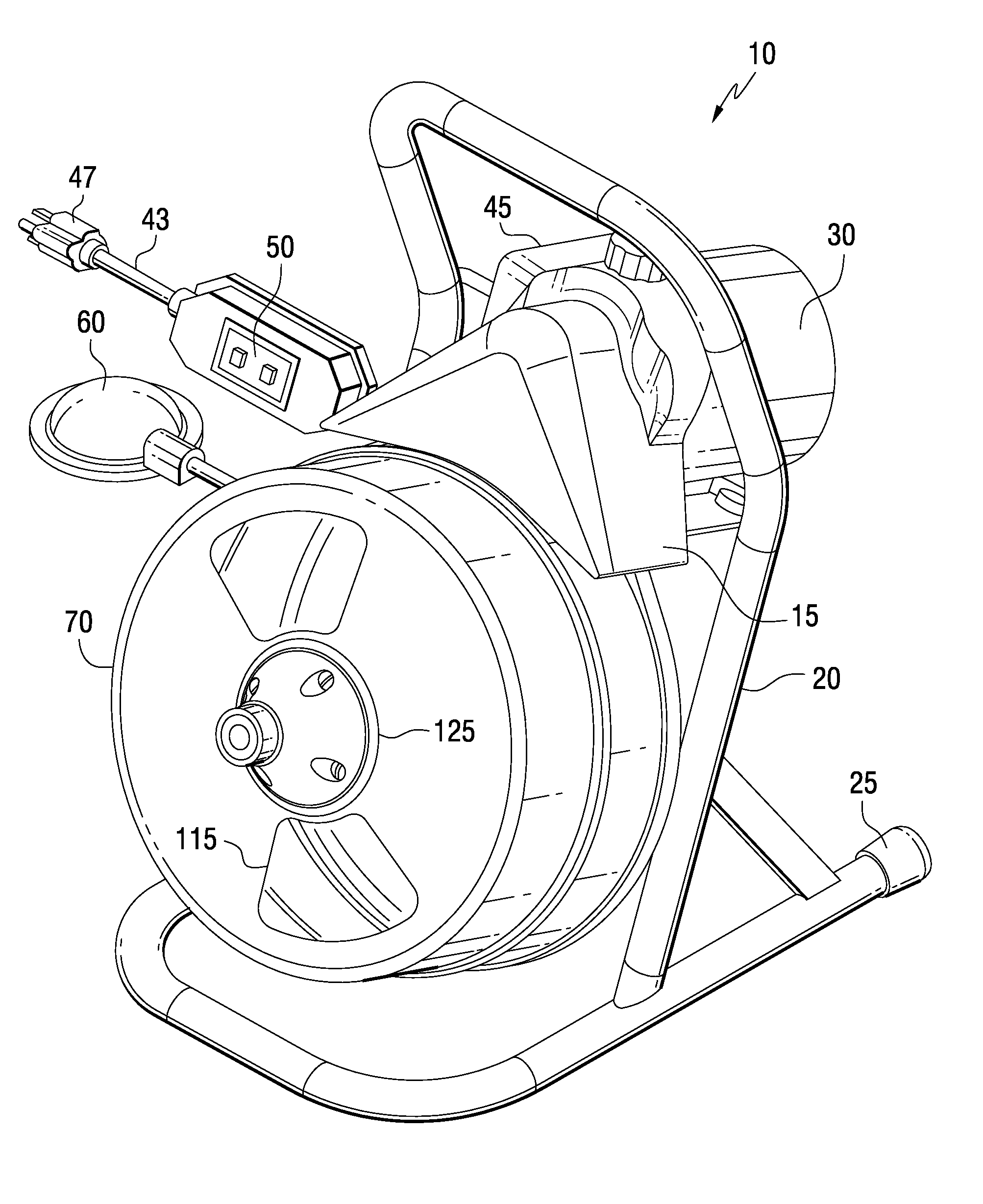
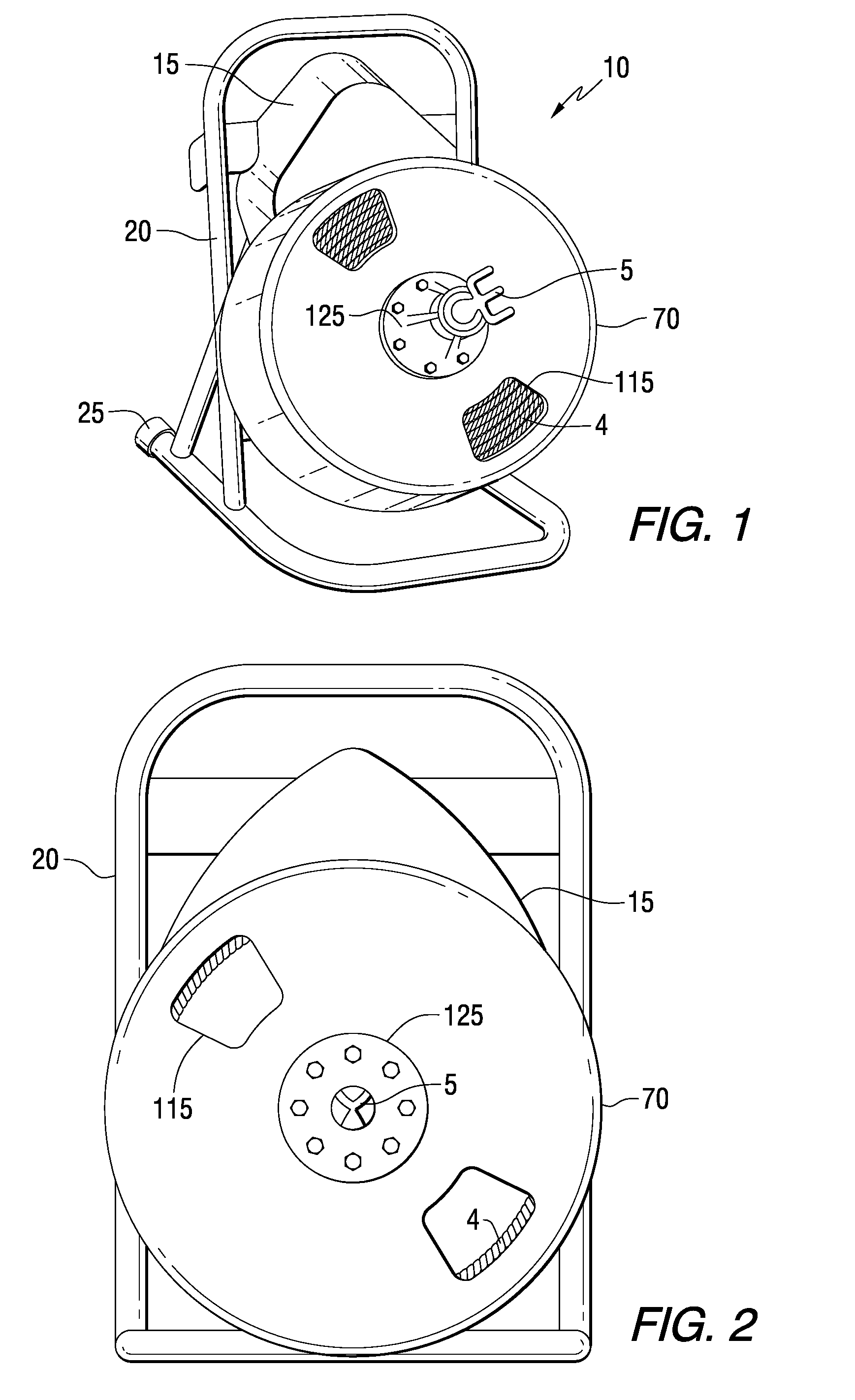
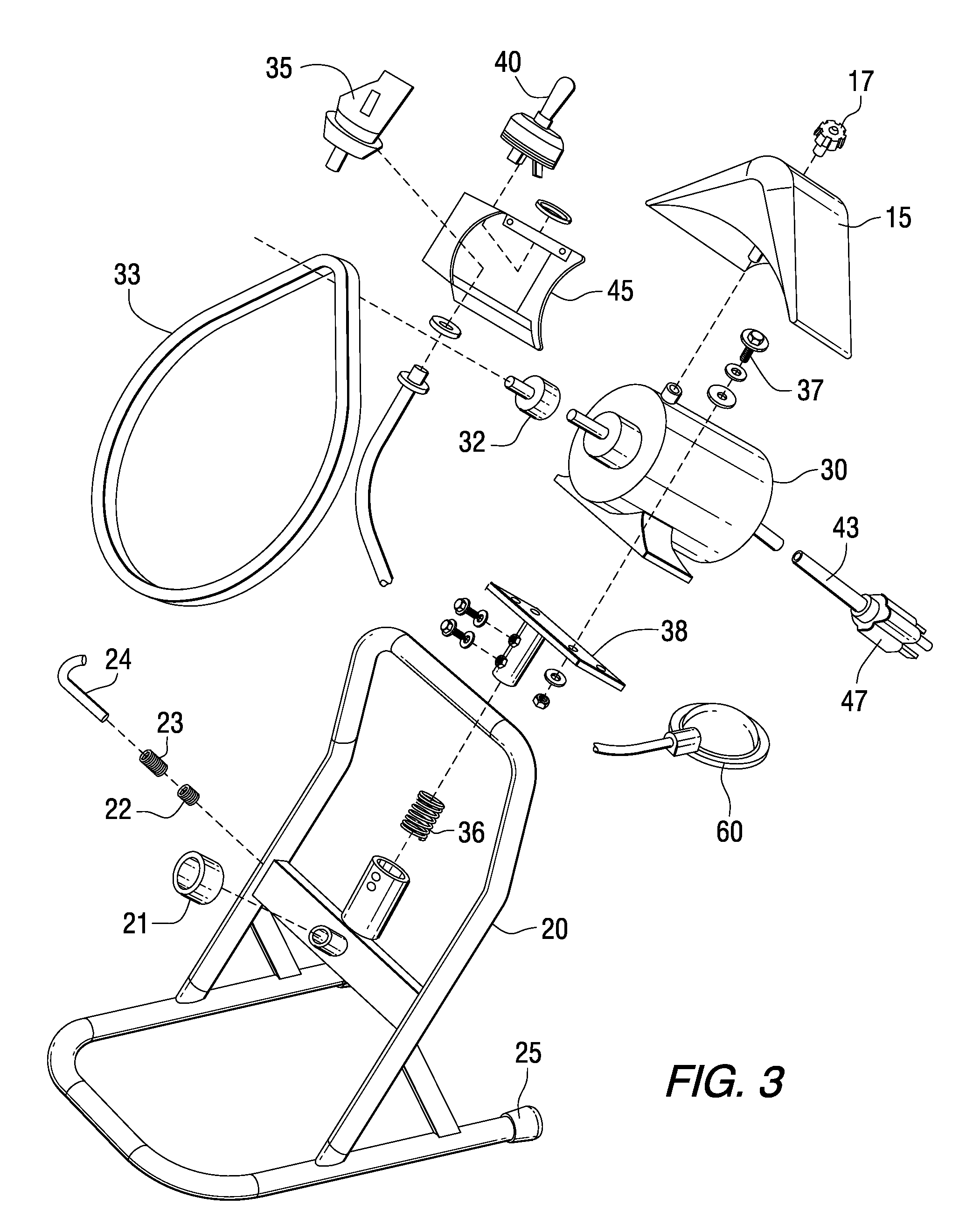
[0037]Referring in greater detail to the drawings, which are illustrations of preferred embodiments of the invention only and are not for limiting the invention, FIGS. 1-4 and FIG. 9-11 present a typical belt driven drum auger machine 10 having a frame 20. The frame is lightweight and portable and may have wheels attached to it. Rubber leg tips 25 increase stability of frame 20 and the machine 10.

[0038]Motor 30 is attached to a motor support 38 with guide screws 37. The motor support 38 attaches to the frame 20. A motor support spring 36 acts as a shock absorber between the motor support 38 and the frame 20. A V belt pulley 32 attaches to the front of the motor 30. A V belt 33 attaches and wraps around the V belt pulley 32 and drum shell 70 therein translating the forces of the motor 30 to the drum shell 70. The drum shell rotates about its drum axis.

[0039]The distributor tube 100 is attached inside drum shell 70 and allows the snake 4 to be pulled to and distributed from the center...


PUM


Abstract

A rotatable, portable drum auger drain cleaning device includes a rotational control which is biased towards the off position. The rotational control device is utilized in conjunction with a motor and the drum to direct drum rotation. The rotational control is typically biased in the off position making it the default position. The rotational control must therefore be manually moved to either a forward or reverse position. When in the forward position, the rotational control can be locked, and when in the reverse position, the switch must be manually held in position or the switch will return to the off position.

Description

FIELD OF THE INVENTION[0001]The present invention relates to a pipe, drain, or sewer cleaning apparatus and devices and, more particularly, to improvements in portable, motor operated drum augers.BACKGROUND AND DESCRIPTION OF THE PRIOR ART[0002]Portable drain cleaning devices are well known, being used by both professional plumbers and by the general public. Such drain cleaning devices generally include a snake, typically constituting a coiled cable, which may further be coiled inside a housing or drum from which an end of the snake protrudes from for the introduction into a pipe, sewer, drain or conduit. Often a tool is attached to the end of the snake entering the pipe or conduit, which aids in removing obstructions, for example by cutting away at the obstruction. Various tools may be interchanged with the end of the snake. The snake has the ability to rotate about its longitudinal axis as well as the ability to be axially displaced along such axis thereby creating a force used to...

Claims


Application Information

Patent Timeline
Patent Type & Authority Patents(United States)
IPC IPC(8): B08B9/045B08B1/04B08B9/047
CPCB08B9/045
Inventor SILVERMAN, DAVIDSILVERMAN, MICHAELPFEIFFER, ANTON D.
Owner GEN WIRE SPRING
Why Eureka
Try Eureka