Measured-signal repetition frequency detection method, and sampling apparatus and waveform observation system using the method

a detection method and signal technology, applied in the direction of frequency measurement arrangement, spectral/fourier analysis, instruments, etc., can solve the problems of inability to correctly reproduce waveforms, process cannot be correctly executed, and the waveform phase cannot be correctly grasped, so as to achieve high accuracy and high accuracy. , the effect of high accuracy

Inactive Publication Date: 2011-05-03
ANRITSU CORP
View PDF12 Cites 4 Cited by
  • Summary
  • Abstract
  • Description
  • Claims
  • Application Information

AI Technical Summary

Benefits of technology

[0090]Generally, ΔFh may be accurately measured by lengthening the measurement time and thus improving the resolution of the spectrum analysis.
[0095]An object of the invention is to solve these problems and provide a method of detecting the repetition frequency of a measured signal whereby the frequency of the signal can be accurately detected from the sampling result even in the presence of a frequency fluctuation in the measured signal, and a sampling apparatus and a waveform observation system using the method whereby the waveform information can be stably acquired and observed while at the same time making it possible to easily simplify the system as a whole.
[0175]As described above, in the measured-signal repetition frequency detection method according to this invention, the provisional repetition frequency of the measured signal is determined from the frequency change amount of a specified signal obtained at the time of sampling by changing the sampling frequency from the provisional sampling frequency by a minuscule amount not causing the frequency fold, and the frequency change amount of the specified signal is detected by sequentially sampling the measured signal at the sampling frequency changed from the provisional sampling frequency so greatly as to cause the frequency fold. Based on the frequency change amount of the specified signal thus detected and the change amount of the sample number indicating how many times the frequency fold has occurred in this process, the error contained in the sample number with the frequency fluctuation contained in the measured signal is calculated, and based on the error contained in the sample number, the provisional repetition frequency of the measured signal is corrected thereby to calculate the regular repetition frequency of the measured signal. Even in the presence of a frequency fluctuation in the measured signal, therefore, the repetition frequency of the waveform of the measured signal can be detected with high accuracy.
[0176]Also, in the measured-signal sampling apparatus and the waveform observation system according to the invention, the sampling frequency is accurately set for the signal of an unknown frequency using the measured-signal repetition frequency detection method described above, so that even in the presence of a frequency fluctuation in the measured signal, the measured signal can be sampled with high accuracy, while at the same time making possible the waveform observation of the measured signal with high accuracy.

Problems solved by technology

Also, in the averaging mode, the averaging process cannot be correctly executed and the waveform cannot be correctly reproduced, while at the same time making it impossible to correctly grasp the waveform phase and the size of the amplitude variation.
In some cases where the correct value, not the approximate value, of the repetitive period of the waveform or the frequency of the measured signal to be observed is unknown, however, the correct sampling period cannot be set for the waveform of the measured signal to be observed, thereby posing the problem that the waveform cannot be observed as desired.
Also, in this type of the waveform observation device, an optical mixer or the like for generating the optical sampling pulse having a narrow width or mixing the light with each other is required, thereby posing another problem that the whole device including the display unit is complicated and increased in cost.

Method used


Image

  • Measured-signal repetition frequency detection method, and sampling apparatus and waveform observation system using the method
  • Measured-signal repetition frequency detection method, and sampling apparatus and waveform observation system using the method
  • Measured-signal repetition frequency detection method, and sampling apparatus and waveform observation system using the method

Examples


first embodiment

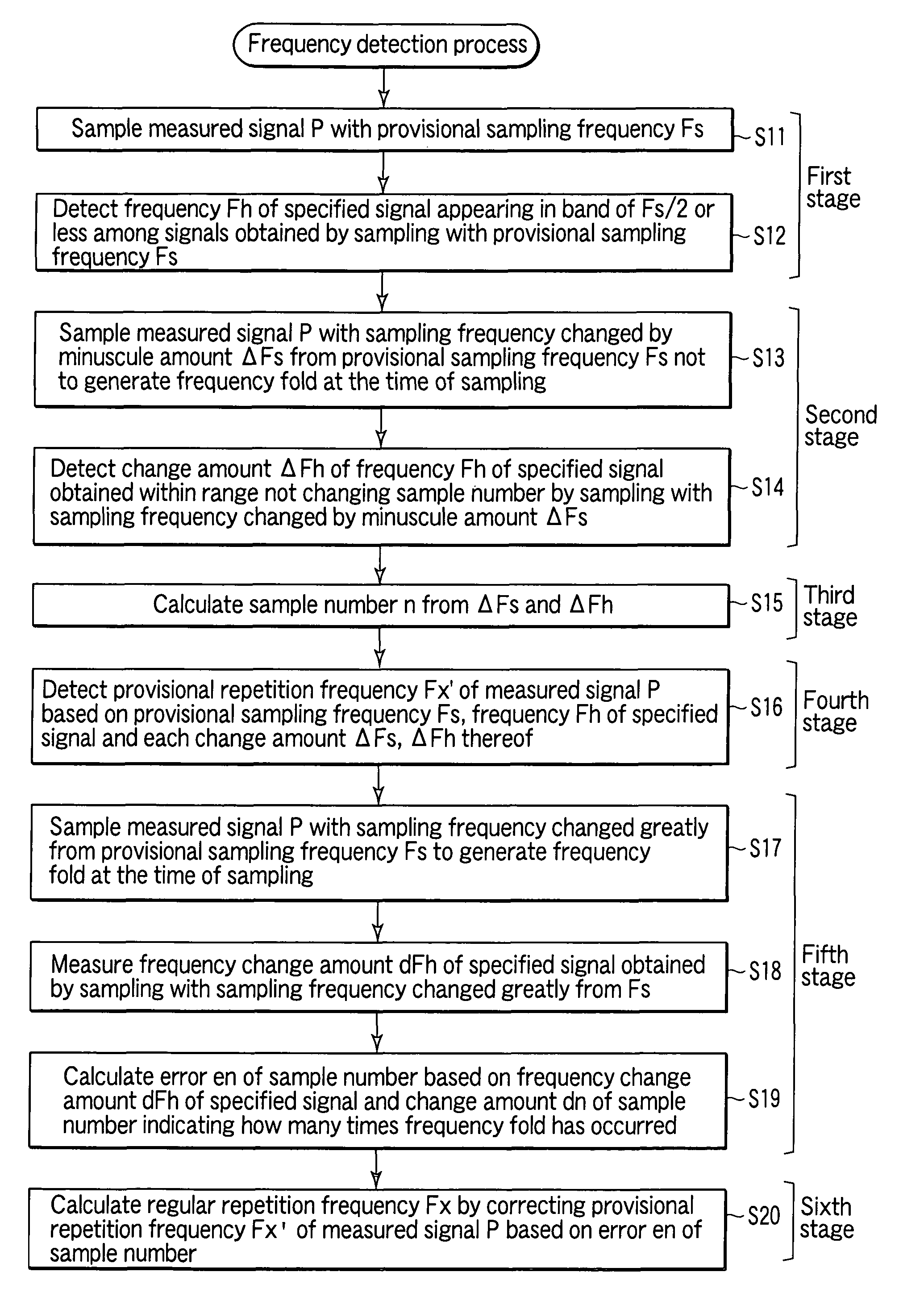
[0197]FIG. 1 is a flowchart shown for explaining the steps of a measured-signal repetition frequency detection method according to a first embodiment of the invention.

[0198]The measured-signal repetition frequency detection method according to the invention basically is characterized by including a first stage (S11, S12) for detecting a frequency Fh of a specified signal appearing in the band not more than one half of a provisional sampling frequency Fs among the signals obtained by sampling the measured signal with the provisional sampling frequency Fs; a second stage (S13, S14) for calculating a frequency change amount ΔFh of the specified signal obtained by the sampling frequency changed from the provisional sampling frequency Fs by a minuscule frequency ΔFs not generating a frequency fold at the time of sampling; a third stage (S15) for calculating a sample number n from Equation (1):

n=ΔFh / ΔFs  (1)

having the denominator equal to the minuscule frequency ΔFs in the second stage (S...

second embodiment

[0229]FIG. 4 is a block diagram shown for explaining the configuration of a waveform observation system including a measured-signal sampling apparatus according to a second embodiment of the invention.

[0230]This waveform observation system 20 according to the second embodiment, like the waveform observation system 20 including the measured-signal sampling apparatus similar to the Japanese prior application filed by the present inventor shown in FIG. 15, in order to execute steps S11 to S14 and S16 of the measured-signal repetition frequency detection method according to the first embodiment described above, specifically includes, as shown in FIG. 4, a parameter designation unit 22, an arithmetic unit 23, a signal generating unit 24, a sampling pulse generating unit 25, an optical sampling unit 26, a specified signal frequency detector 27 and a provisional repetition frequency calculation unit (in FIG. 15, the repetition frequency calculation unit) 28.

[0231]Also, the waveform observa...

third embodiment

[0274]FIG. 9 is a block diagram shown for explaining the configuration of a waveform observation system including a measured-signal sampling apparatus according to a third embodiment of the invention.

[0275]A waveform observation system 40 including the measured-signal sampling apparatus according to the third embodiment has such a configuration that the sampling apparatus 21 included in the waveform observation system 20 according to the second embodiment and the function of the digital oscilloscope 60 are accommodated in the same housing and integrated with each other.

[0276]Specifically, the waveform observation system 40 including the measured-signal sampling apparatus according to the third embodiment includes, in addition to each component element of the sampling apparatus 21 shown in FIG. 4 above, an A / D converter 43, a data acquisition control unit 44, a waveform data memory 45, a display control unit 46, a display unit 47 and an observation mode designation unit 48.

[0277]The ...


PUM


Abstract

In a method of detecting a repetition frequency of a measured signal, in order to detect the waveform repetition frequency of the measured signal with high accuracy even in the presence of a frequency fluctuation in the measured signal, the repetition frequency of the measured signal acquired by the conventional method is used as a provisional repetition frequency, and the frequency change amount of the specified signal obtained in the case where the measured signal is sampled sequentially with a sampling frequency greatly changed from the provisional sampling frequency to generate a frequency fold at the time of sampling is detected. Based on the detected frequency change amount of the specified signal and the change amount of the sample number indicating how many times the frequency fold has occurred in the process, the error contained in the sampling number with a frequency fluctuation contained in the measured signal is calculated. Then, based on the error contained in this sample number, the provisional repetition frequency of the measured signal is corrected, thereby calculating the regular repetition frequency of the measured signal.

Description

[0001]This application is a U.S. National Phase Application under 35 USC 371 of International Application PCT / JP2008 / 050906 filed Jan. 23, 2008.TECHNICAL FIELD[0002]The present invention relates to a method for detecting a repetition frequency of a measured signal and a sampling apparatus and a waveform observation system using the method, and in particular, to a measured-signal repetition frequency detection method and a sampling apparatus and a waveform observation system using the method, in which an optical signal modulated by a high-speed repetitive signal is sampled thereby to acquire and observe the waveform information thereof, and in which a technique is employed to acquire and observe stable waveform information by accurately detecting the frequency of the measured signal even in the presence of a frequency fluctuation of the measured signal.BACKGROUND ART[0003]In order to acquire and observe the waveform data of the optical signal modulated by a high-speed repetitive sign...

Claims


Application Information

Patent Timeline
Patent Type & Authority Patents(United States)
IPC IPC(8): G01R23/00
CPCG01R13/0272G01R19/2509G01R23/14
Inventor TSUDA, YUKIO
Owner ANRITSU CORP
Why Eureka
Try Eureka