
Method and system for isolating and reducing grating lobe interference

a technology of interference and grating lobe, applied in direction finders, instruments, non-resonant long antennas, etc., can solve the problems of increasing sensor costs and processing requirements, reducing operational effectiveness in certain cases, and requiring significant sensor hardware costs to reduce grating lobe interference, etc., to achieve the effect of saving sensor hardware cost and weigh

Inactive Publication Date: 2011-05-03
LOCKHEED MARTIN CORP
View PDF3 Cites 1 Cited by
  • Summary
  • Abstract
  • Description
  • Claims
  • Application Information

AI Technical Summary

Benefits of technology

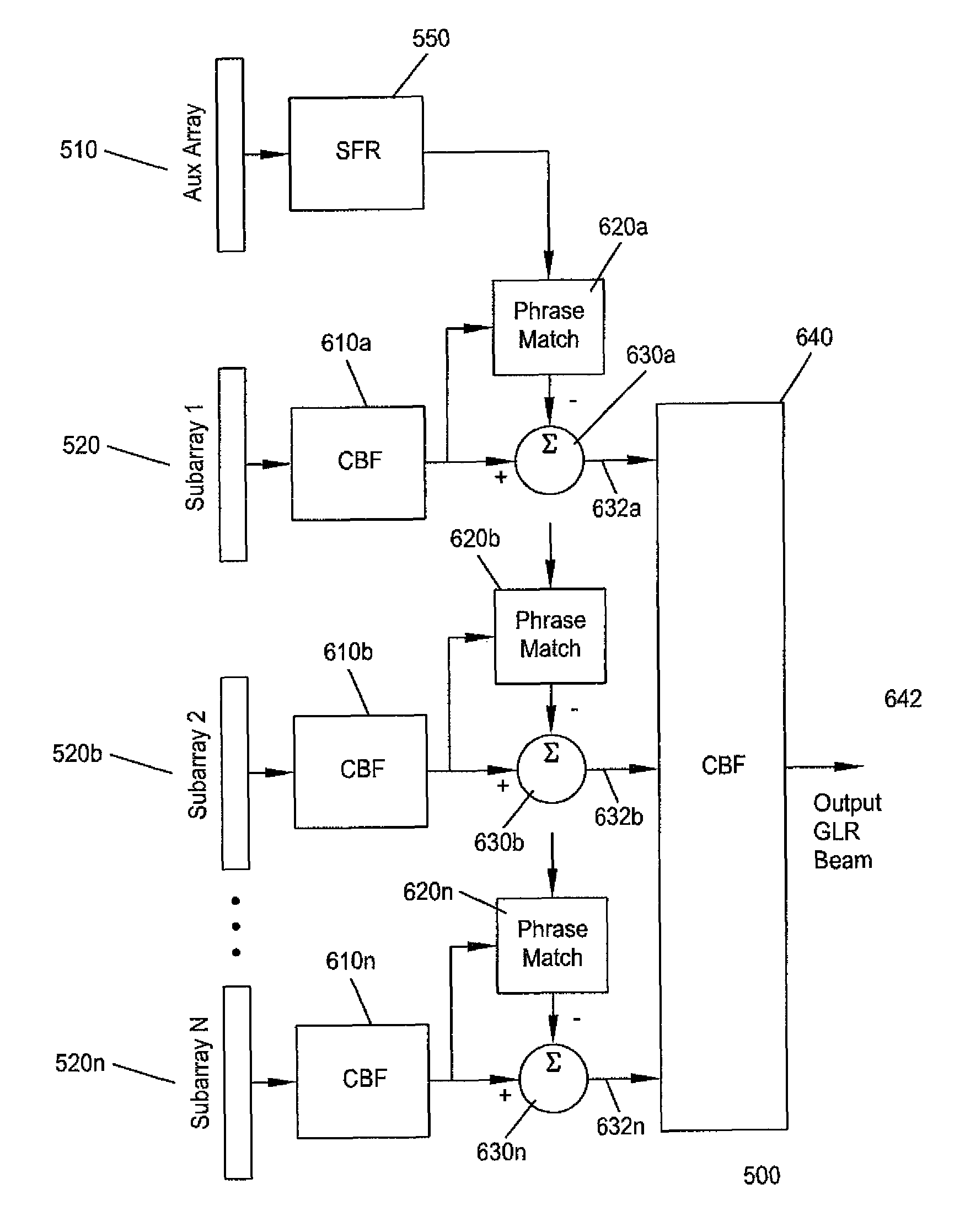
[0009]An exemplary embodiment of the invention contemplates use of a sufficiently sampled auxiliary array in combination with one or more under-sampled sub-arrays to reject grating lobe interference. The exemplary embodiment uses the smaller but sufficiently-sampled auxiliary array to create a signal-free reference (SFR) beam that only contains information from a grating lobe. In another aspect of an exemplary embodiment of the invention the SFR is used to cancel the interfering grating lobe in the under-sampled main beam by applying an estimate of the phase shift between the two and coherently eliminating or subtracting the phase-shifted signal-free reference from the main beam. Exemplary aspects of the invention thus support significant under population of the full aperture and avoid the problems and limitations of previous solutions, with consequent savings in sensor hardware cost and weight.

Problems solved by technology

Grating lobes are artifacts or a form of aliasing that result when a uniformly spaced array is operated above its half-wavelength design frequency.
The most basic approach simply involves raising the design frequency by decreasing channel-spacing over the entire array thereby raising sensor costs and processing requirements.
The approach in this situation is simply to avoid steering beyond 70 degrees, which limits operational effectiveness in certain cases.
Current methods for reducing grating lobe interference either require significant sensor hardware costs, merely attempt to avoid the problem, or introduce a host of additional problems.

Method used


Image

  • Method and system for isolating and reducing grating lobe interference
  • Method and system for isolating and reducing grating lobe interference
  • Method and system for isolating and reducing grating lobe interference

Examples


Embodiment Construction

[0019]Reference will now be made in detail to the present exemplary embodiments of the invention, examples of which are illustrated in the accompanying drawings.

[0020]Referring to FIG. 5, a graph is shown illustrating an exemplary embodiment of the invention. A line array 500 is shown separated into an auxiliary-array 510, a first sub-array 520a, and a second sub-array 520b. While only two sub-arrays are shown it is to be understood that any number of sub-arrays may be used. The sub-arrays 520a and 520b each comprise M elements 522a-n. The auxiliary array 510 comprises 2M elements 512a-n. It is to be understood however that auxiliary array 510 may have any integer multiple of elements of the sub-arrays, depending on the desired maximum operating frequency, also known as the design frequency, of the line array 500. As shown, the first and second sub-arrays 520a and 520b have been under-sampled, meaning that their element spacing is greater that ½ the operating wavelength associated w...


PUM


Abstract

This invention relates to the use of a sufficiently-sampled auxiliary array in combination with one or more under-sampled sub-arrays. The sufficiently-sampled auxiliary array is used to create a signal-free reference (SFR) beam that contains grating lobe interference. The SFR may be used to cancel the interfering grating lobe in an under-sampled main beam by coherently eliminating or subtracting the SFR from the main beam. Exemplary aspects of the invention thus support significant under population of the full aperture and avoid the problems and limitations of previous solution, with consequent savings in sensor hardware cost and weight.

Description

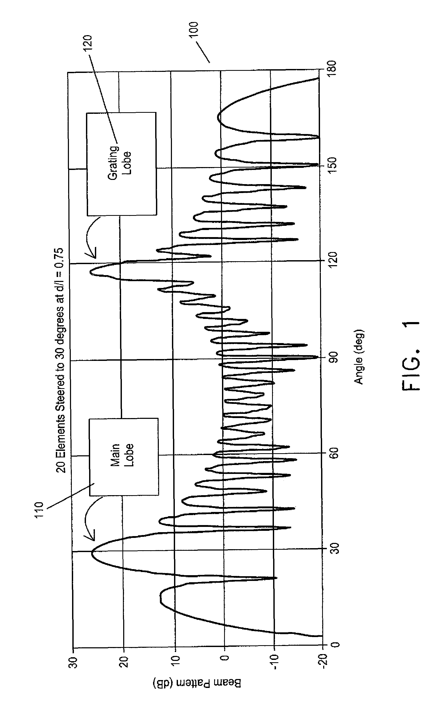
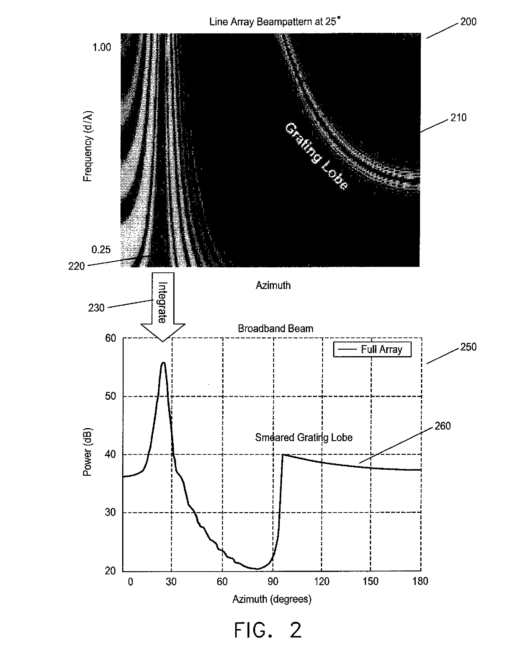
FIELD OF INVENTION[0001]This invention relates generally to the field of line array sensors and specifically to isolating and reducing grating lobe interference.BACKGROUND[0002]When beamforming a line array having uniformly spaced elements, grating lobes can appear if the element spacing exceeds one-half (½) of a wavelength. This effect is analogous to the aliasing that occurs when sampling time data at less than the Nyquist rate. In a narrowband sense, grating lobes introduce ambiguity. When wideband beamforming, these narrowband grating lobes smear out across bearing and raise the overall background level. This invention serves to cancel grating lobes, thus enabling operation of line arrays in a band above the ½ wavelength design frequency.[0003]Referring to FIG. 1, a graph illustrating an exemplary beam pattern 100 associated with a line array having an under-sampled uniform element spacing, a spacing that exceeds half the wavelength associated with the design frequency of the ar...

Claims


Application Information

Patent Timeline
Patent Type & Authority Patents(United States)
IPC IPC(8): G01S3/16H01Q3/00
CPCG10K15/04H01Q3/2611H01Q21/08H01Q11/10H01Q3/36
Inventor BARNARD, THOMAS J.CANAVAN, THOMAS M.
Owner LOCKHEED MARTIN CORP
Learn More