Eureka AIR delivers breakthrough ideas for toughest innovation challenges, trusted by R&D personnel around the world.

Mutual symmetry detection

a symmetry detection and multi-symmetric technology, applied in the field of geometric pattern matching, can solve the problems of difficult to distinguish correlations between rotated and/or reflected versions, high computational cost, and high computational cost of current methods for determining such symmetry

Active Publication Date: 2011-05-03
NATIONAL INSTRUMENTS
View PDF16 Cites 4 Cited by
  • Summary
  • Abstract
  • Description
  • Claims
  • Application Information

AI Technical Summary

Benefits of technology

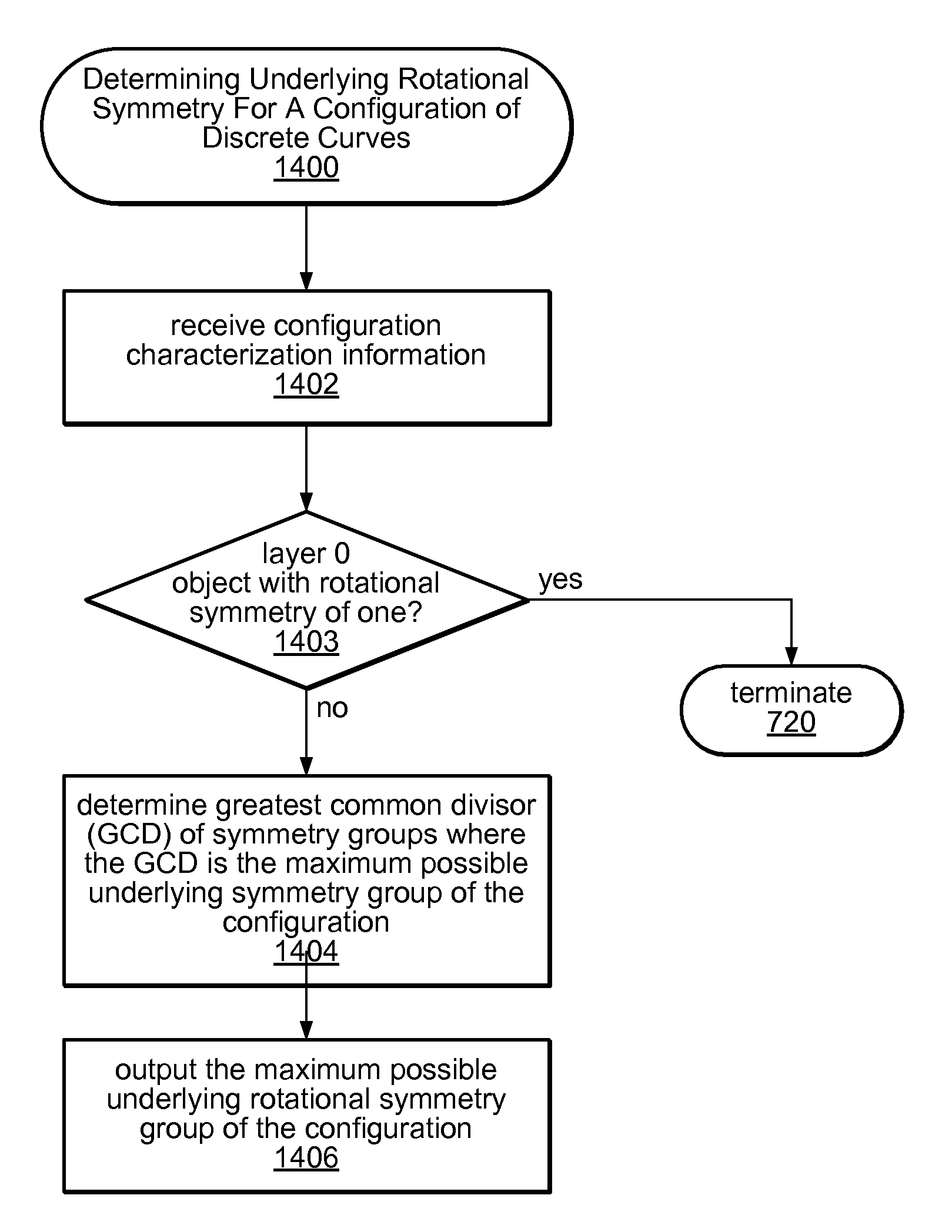
[0021]Finally, the maximum possible object-based mutual rotational symmetry group for the configuration may be stored, e.g., to a memory medium. The maximum possible object-based mutual rotational symmetry group may then be usable to perform pattern matching between configurations, for example, to efficiently cull non-matching configurations, as discussed at length below.
[0024]First, the above method may be performed, resulting in storage of the maximum possible object-based mutual rotational symmetry group for the configuration of discrete curves, where the maximum possible object-based mutual rotational symmetry group is usable to perform pattern matching between configurations

Problems solved by technology

This approach is thus very computationally intensive.
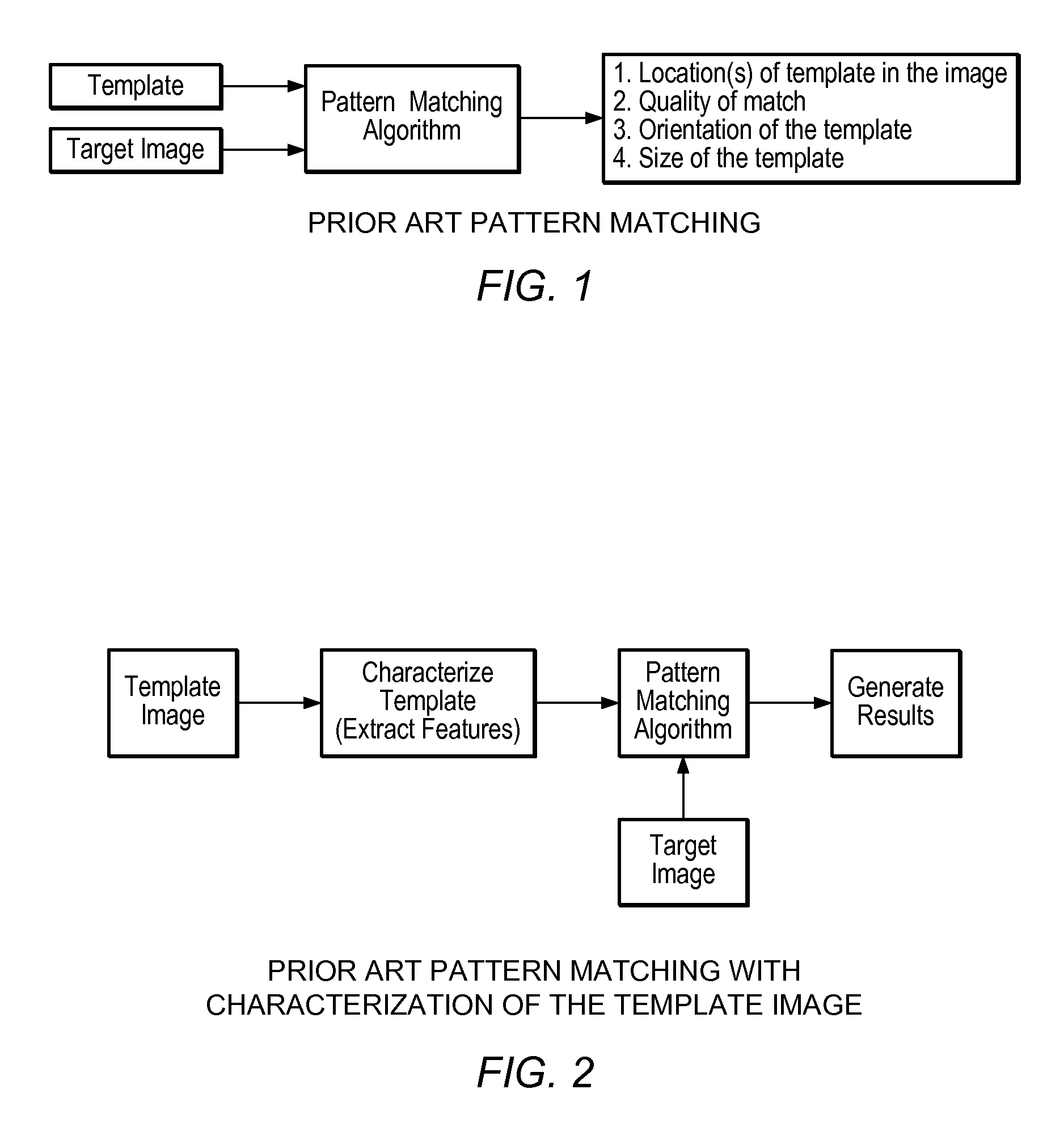
An issue that arises in many pattern matching applications is that the image objects being analyzed, e.g., the template images and / or the target images, may include various symmetries, e.g., rotational symmetries, where, for example, a first object is a rotated version of a second object, or where a configuration of equivalent objects includes rotational symmetries, and / or reflection symmetries, where a first object is a reflected version of a second object.
Current methods for determining such symmetries are computationally intensive and error prone, in that correlations between rotated and / or reflected versions are often difficult to distinguish.

Method used


Image

  • Mutual symmetry detection
  • Mutual symmetry detection
  • Mutual symmetry detection

Examples


Embodiment Construction

Incorporation by Reference

[0076]The following patent applications are hereby incorporated by reference in their entirety as though fully and completely set forth herein:

[0077]U.S. application Ser. No. 10 / 455,141, titled “Discrete Curve Symmetry Detection”, filed Jun. 5, 2003.

[0078]U.S. patent application Ser. No. 10 / 263,560 titled “Pattern Matching System Utilizing Discrete Curve Matching with a Mapping Operator”, filed Oct. 3, 2002, and which issued as U.S. Pat. No. 7,171,048 on Jan. 30, 2007.

[0079]U.S. patent application Ser. No. 10 / 454,940, titled “Rotational Symmetry Detection for Configurations of Discrete Curves”, filed Jun. 5, 2003, and which issued as U.S. Pat. No. 7,212,673 on Jan. 30, 2007.

[0080]The following publications are hereby incorporated by reference in their entirety as though fully and completely set forth herein:

[0081]The National Instruments IMAQ™ IMAQ Vision Concepts Manual; and

[0082]“Efficient Matching Of Discrete Curves”, by Lothar Wenzel, National Instrumen...


PUM


Abstract

System and method for detecting symmetries of configurations of discrete curves. Configuration characterization information for a configuration of a plurality of discrete curves is received, where the configuration characterization information comprises rotational symmetry groups for each of the plurality of discrete curves. A greatest common divisor of the rotational symmetry groups of the discrete curves is determined, where the greatest common divisor is a maximum possible object-based mutual rotational symmetry group for the configuration. The determined value is stored, and is usable to perform pattern matching between configurations. This value may be compared to that of a target configuration to determine if the two configurations can match. Additional symmetry-based matching techniques are used to perform staged pattern matching between the two configurations, where the process may terminate as soon as one of the techniques determines that the configurations cannot match, or a matching algorithm determines that they match.

Description

PRIORITY AND CONTINUATION INFORMATION[0001]This application is a continuation-in-part of U.S. application Ser. No. 10 / 455,141, titled “Discrete Curve Symmetry Detection”, filed Jun. 5, 2003 now U.S. Pat. No. 7,269,286, whose inventors were Lothar Wenzel and Mark S. Williams.FIELD OF THE INVENTION[0002]The present invention relates to geometric pattern matching in general, and more particularly to a system and method for detecting symmetries in and among discrete curves, e.g., in configurations of discrete curves.DESCRIPTION OF THE RELATED ART[0003]In many applications it is necessary or desired to determine the presence of an object of interest in a data set, such as a target image. For example, in many image processing applications it is desirable to find one or more matches of a template image in a larger target image. Exemplary machine vision applications include process monitoring, feedback control, and laboratory automation; image and video compression; and jitter compensation ...

Claims


Application Information

Patent Timeline
Patent Type & Authority Patents(United States)
IPC IPC(8): G06K9/46G06K9/62G06K9/68G06V10/42G06V10/46
CPCG06K9/4609G06K9/52G06K9/48G06V10/443G06V10/42G06V10/46
Inventor WENZEL, LOTHAR
Owner NATIONAL INSTRUMENTS
Why Eureka
Eureka Blog
Learn More