Heat engines

a heat engine and heat sink technology, applied in the field of heat engines, can solve the problems of large temperature gradient along the circumference of the housing, internal combustion engine, and not working in cycles, and achieve the effects of increasing power output, facilitating heat transfer, and increasing heat transfer duration

Inactive Publication Date: 2011-05-10
CAO YIDING
View PDF26 Cites 6 Cited by
  • Summary
  • Abstract
  • Description
  • Claims
  • Application Information

AI Technical Summary

Problems solved by technology

Unlike a heat engine that employs a working fluid without the change of chemical compositions, an internal combustion engine, strictly speaking, does not work in cycles due to the change in chemical composition of the working fluid.
Turning now to a rotary combustion engine such as a Wankel rotary combustion engine, one of the difficulties is the cooling of rotor seals.
Additionally in a rotary engine, the engine housing is constantly heated on the side of combustion chamber and cooled on the side of intake port, leading to a large temperature gradient along the circumference of the housing, which may cause uneven thermal expansion.

Method used


Image

  • Heat engines
  • Heat engines
  • Heat engines

Examples


Embodiment Construction

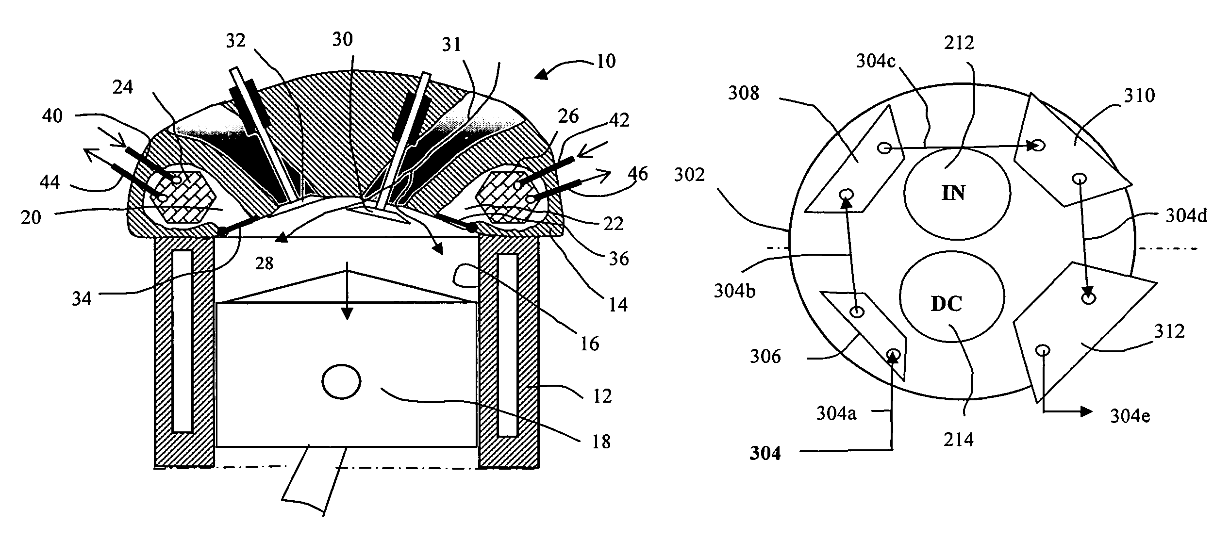
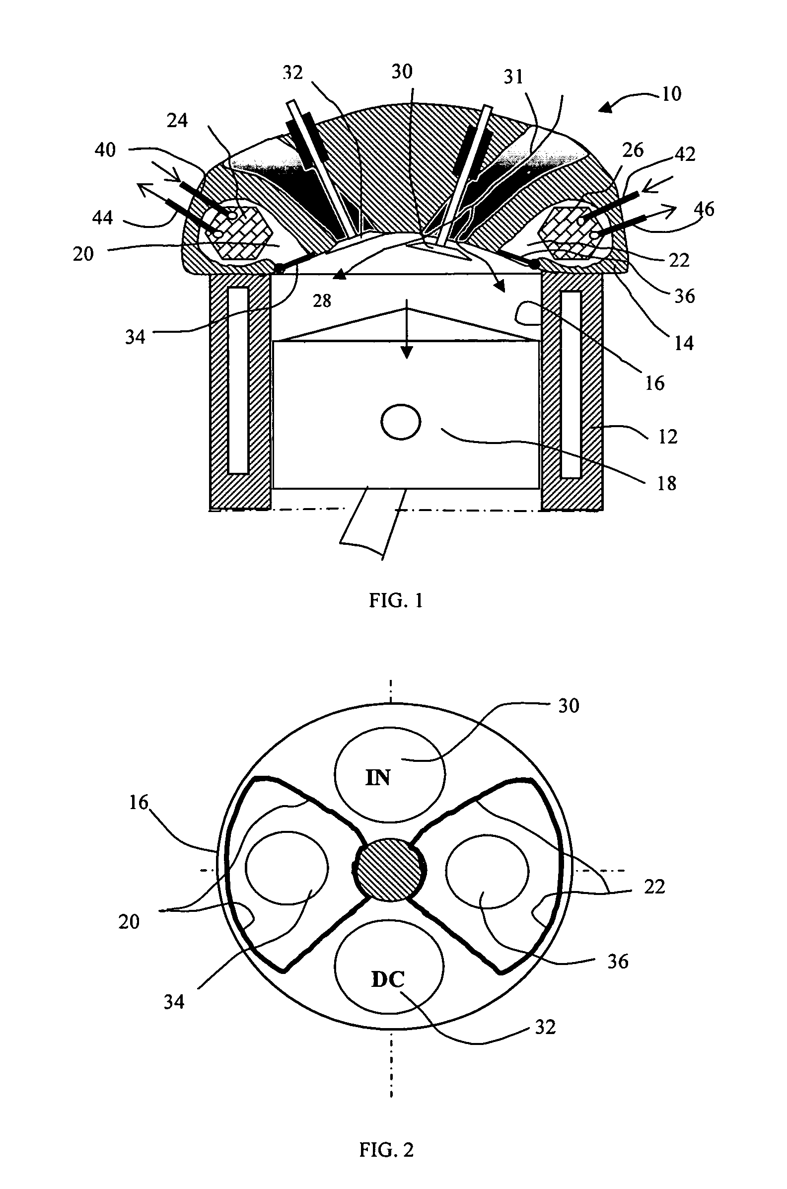
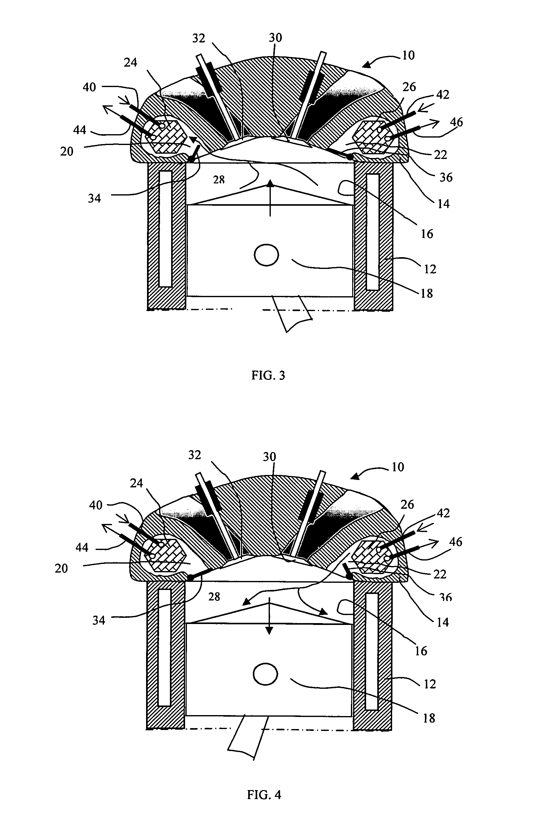
[0051]FIG. 1 illustrates a heat engine 10 in accordance with the present invention, which includes a cylinder block 12 and a cylinder head 14. The cylinder block 12 contains at least a cylinder 16 and a piston 18 that is slidably disposed within the cylinder 16. Associated with each engine cylinder 16, the cylinder head 14 defines a first heating chamber 20 and a second heating chamber 22. Furthermore, associated with the heating chambers, a first heat exchanger unit 24 and a second heat exchanger unit 26 are disposed, respectively, within the heating chambers 20 and 22. When the piston 18 reaches the top dead center (TC), cylinder space 28, as defined by the bottom face of the cylinder head 14, the top face of the piston 18, and the sidewall of the cylinder 16, may be minimized. The cylinder head is provided with an intake port and a discharge port, and the intake port has an intake valve 30, and the discharge port has a discharge valve 32. Additionally, the first heating chamber 2...


PUM


Abstract

This invention provides heat engines based on the structure of internal combustion engines and employs a gaseous working fluid without combustion. The heat engine comprises at least a piston and cylinder assembly and each cylinder has at least an associated heating chamber with a heat exchanger unit being disposed therewithin. The chamber may have at least a chamber valve to establish or block the flow of the gaseous working fluid between the heating chamber and cylinder space. The engine is adapted to operate on cycles that enable heat transfer from a heat source to the working fluid while being enclosed within the heating chamber and provides substantially increased heat transfer duration before the power stroke. Therefore the engine may produce sufficiently high power output with reasonably high thermal efficiency.

Description

CROSS REFERENCES TO RELATED APPLICATIONS[0001]This application is a continuation of provisional application 60 / 876,751 filed Dec. 22, 2006.FIELD OF INVENTION[0002]This invention relates to heat engines that convert thermal energy into mechanical energy, in particular related to thermal engines using a gas as the working fluid.BACKGROUND[0003]A heat engine is an energy system that performs the conversion of thermal energy from a heat source or heat reservoir to mechanical work. A variety of heat sources may be employed to power a heat engine. These heat sources may include, but not limited to, combustion gases from a combustion chamber, exhaust gases from a diesel engine, gasoline engine, or gas turbine engine, flue gases and hot fluids from industrial furnaces or processes, and various non-combustion heat sources related to solar, geothermal, nuclear, or biological energy.[0004]Unlike a heat engine that employs a working fluid without the change of chemical compositions, an internal...

Claims


Application Information

Patent Timeline
Patent Type & Authority Patents(United States)
IPC IPC(8): F02G3/00F02G1/04F02G1/00F03G6/00F02B75/02
CPCF01B29/10F01C1/22F01C21/06F02G1/02Y02E10/46F02G2242/00F02G2254/30
Inventor CAO, YIDING
Owner CAO YIDING
Why Eureka
Try Eureka