
Fuel filter system

a filter system and fuel technology, applied in the direction of moving filter element filters, filtration separation, separation processes, etc., can solve the problems of filter system hydrophobic properties losing and/or hydrophobic effect declining, and achieve the effect of improving water separation

Active Publication Date: 2011-05-10
MANN HUMMEL GMBH
View PDF7 Cites 35 Cited by
  • Summary
  • Abstract
  • Description
  • Claims
  • Application Information

AI Technical Summary

Benefits of technology

[0005]Another object of the invention is to provide a fuel filter system which avoids the disadvantages described above and ensures highly effective separation over the entire lifetime of the filter element.
[0008]These and other objects are achieved in accordance with the present invention by providing a fuel filter comprising a filter housing, a particle filter element disposed in the housing between a housing inlet and a housing outlet, and a coalescer element for improving separation of water from fuel passed through the filter, the coalescer element being arranged in the housing upstream from the particle filter element so that fuel passing through the filter flows first through the coalescer element and then through the particle filter, wherein the coalescer element has no significant particle filtering properties.
[0009]One of the advantages of this invention is that the coalescer element cannot become clogged by any dirt particles, but instead remains adequately permeable even when there is a very large amount of dirt and retains its coalescing properties over the entire lifetime of the filter element.

Problems solved by technology

One disadvantage of this design is that because of its active filter properties, the main filter element becomes loaded with dirt, which reduces an / or interferes with flow through the filter.
Furthermore, the main filter element loses its coalescent properties over a period of time, which means that on the whole the filter system loses its hydrophobic properties and / or the hydrophobic effect declines until the filter element is replaced.

Method used


Image

  • Fuel filter system
  • Fuel filter system
  • Fuel filter system

Examples


Embodiment Construction

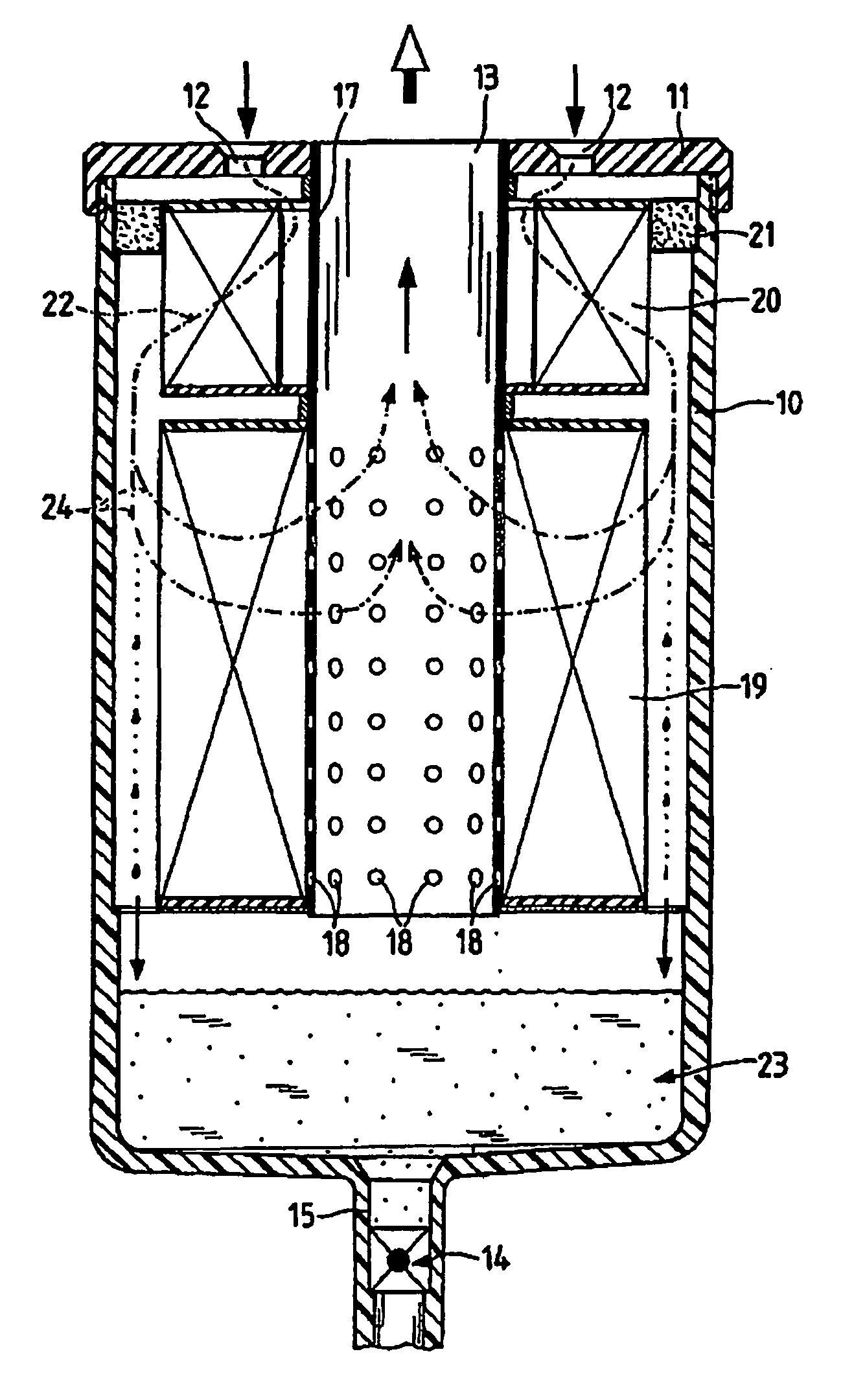
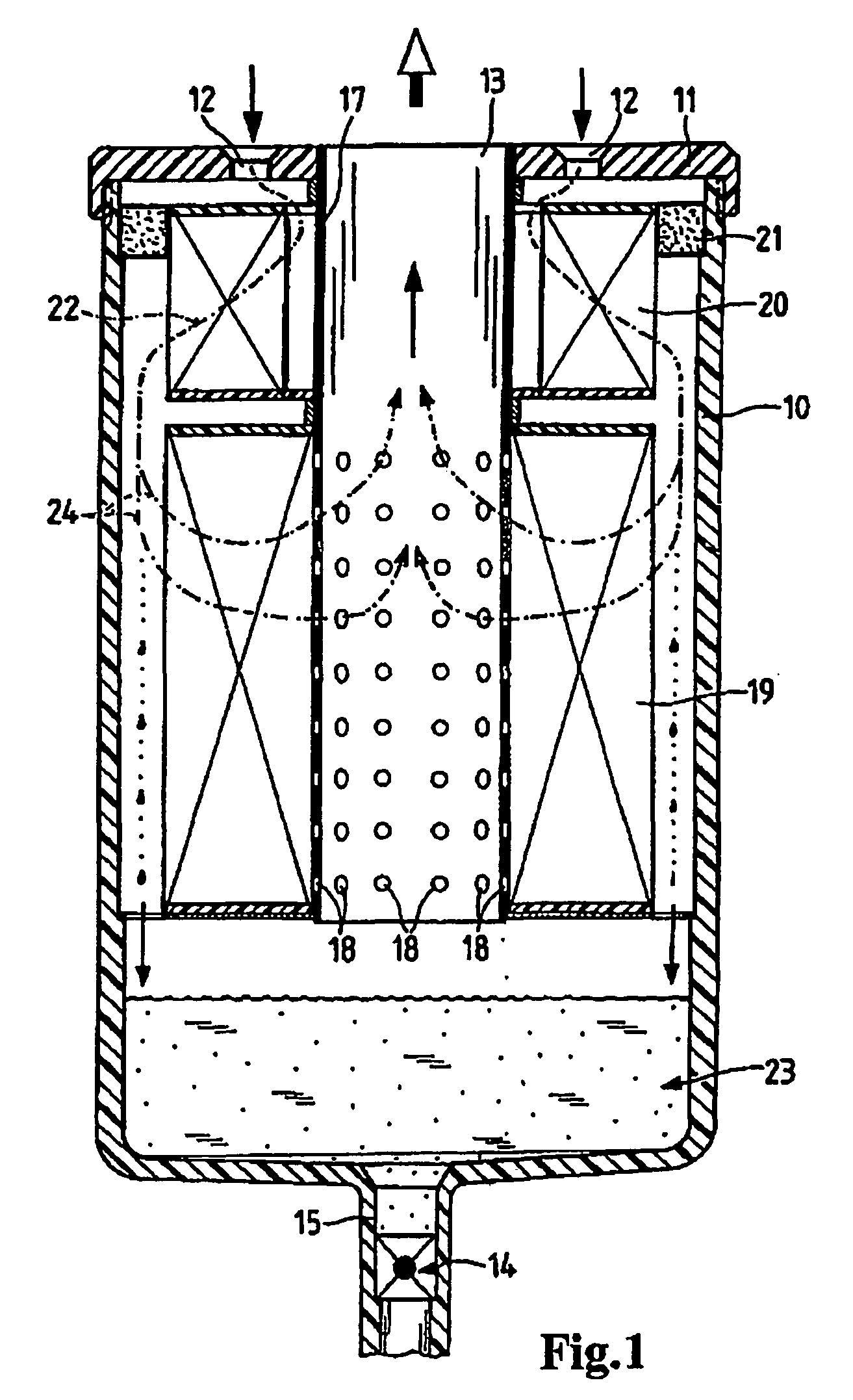
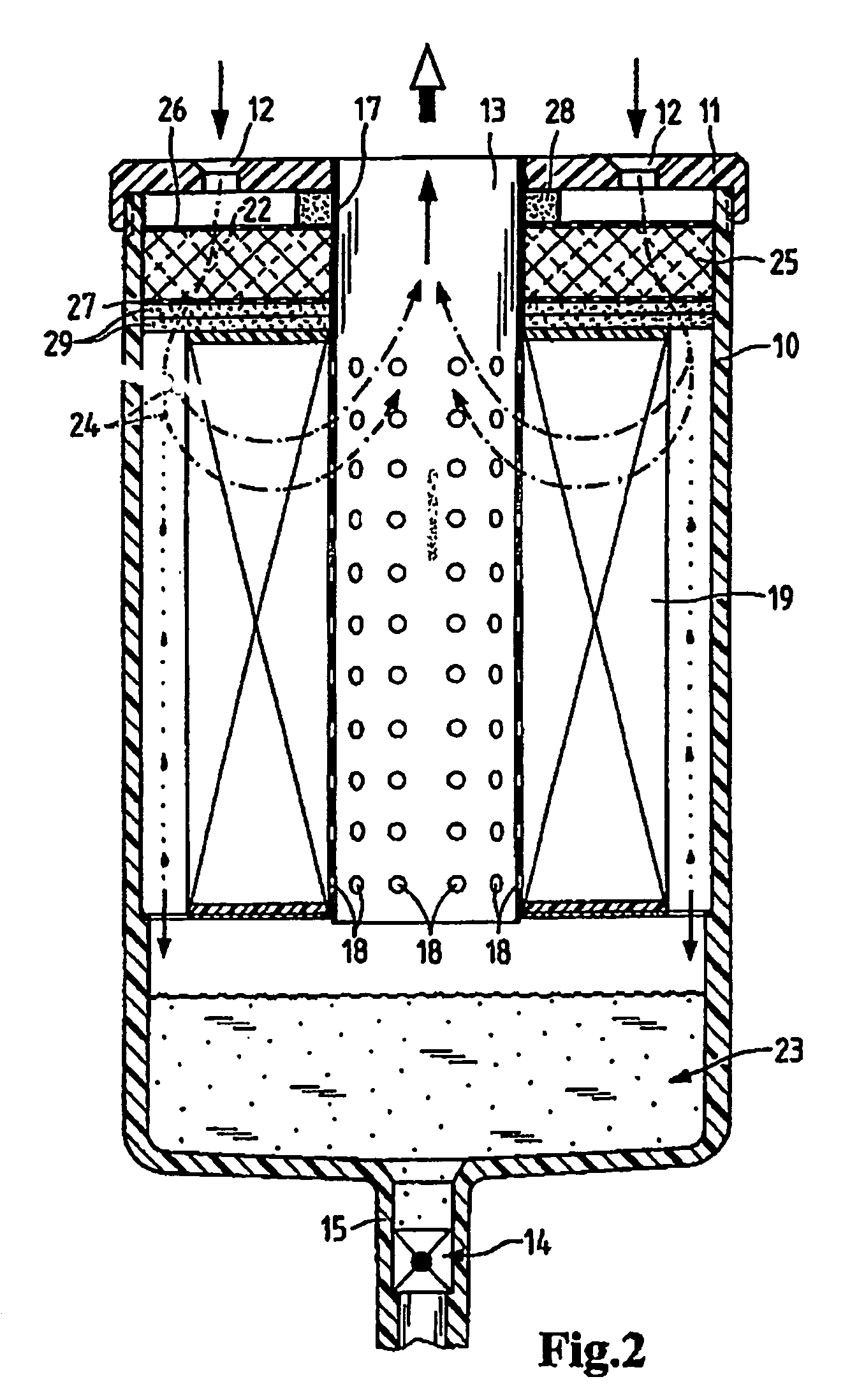
[0019]FIG. 1 shows a fuel filter according to the invention comprising a housing 10 which is constructed essentially in the form of a pot. The upper part of the housing 10 is closed by a cover 11. Cover 11 has inlet openings 12 for fuel to flow in and an outlet opening 13 through which filtered fuel can be removed. A water discharge valve 14 is provided on a pipe connection 15 at the lower end of the housing 10. Inside the housing there is a rising pipe 17, which is permeable, i.e., provided with openings 18, in the area of the particle filter element.

[0020]The particle filter 19 which is placed over the rising pipe 17 is comprised of a filter material folded in zigzag pleats, which can, for example, be composed of a plurality of layers. A coalescer element 20 is provided above the particle filter 19. In the example illustrated here the coalescer element is also made of a material having zigzag pleating. This medium may be a polyester material, a polyamide or another material having...


PUM

PropertyMeasurementUnit
areaaaaaaaaaaa
cylindrical shapeaaaaaaaaaa
hydrophobicaaaaaaaaaa

Abstract

A fuel filter system, particularly a diesel filter, including a housing, a particle filter arranged in the housing, and a coalescer element mounted on the particle filter. Fuel passes successively through the serially connected coalescer and particle filter. The coalescer element improves the separation of any water contained in the fuel to be filtered, while exhibiting no or no significant fuel-filtering properties.

Description

CROSS REFERENCE TO RELATED APPLICATIONS[0001]This application is a continuation of international patent application no. PCT / EP2004 / 050341, filed Mar. 22, 2004 designating the United States of America and published in German as WO 2004 / 082804 on Sep. 30, 2004, the entire disclosure of which is incorporated herein by reference. Priority is claimed based on Federal Republic of Germany patent application no. DE 103 13 867.6, filed Mar. 21, 2003.BACKGROUND OF THE INVENTION[0002]The present invention relates to a fuel filter system, in particular a diesel filter, comprising a particle filter provided in a housing.[0003]U.S. Pat. No. 5,084,170 describes a fuel filter having a housing in which a main filter element and a secondary filter element are provided. Fuel flows through the main filter element from the inside to the outside. In addition, it has coalescing properties so that any water present in the fuel coalesces, i.e., larger droplets of water are formed and enter a water collectin...

Claims


Application Information

Patent Timeline
Patent Type & Authority Patents(United States)
IPC IPC(8): B01D17/04B01D17/022B01D29/56B01D29/58B01D36/00
CPCB01D29/01B01D36/003B01D29/114B01D29/117B01D29/58B01D2201/295Y10S210/05
Inventor KLEIN, GUNNAR-MARCELWEIPPRECHT, UWEKIEDAISCH, STEFFI
Owner MANN HUMMEL GMBH
Learn More