Magnetic head for perpendicular magnetic recording
a perpendicular magnetic and recording technology, applied in the field of magnetic recording head perpendicular magnetic recording, can solve the problems of reducing the flux density of the middle magnetic layer, affecting the quality of the magnetic recording, so as to prevent the reduction of the flux density of the magnetic layer
- Summary
- Abstract
- Description
- Claims
- Application Information
AI Technical Summary
Benefits of technology
Problems solved by technology
Method used
Image
Examples
first embodiment
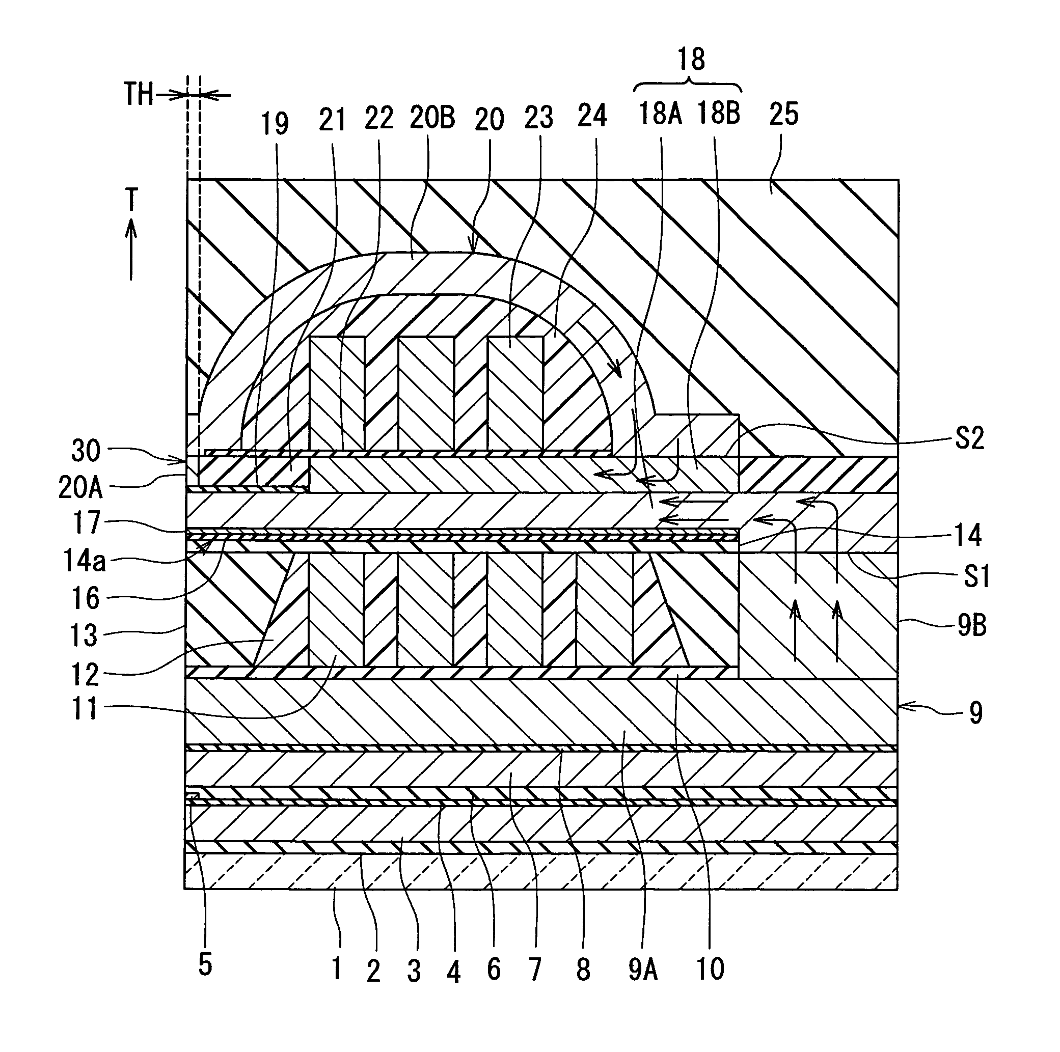
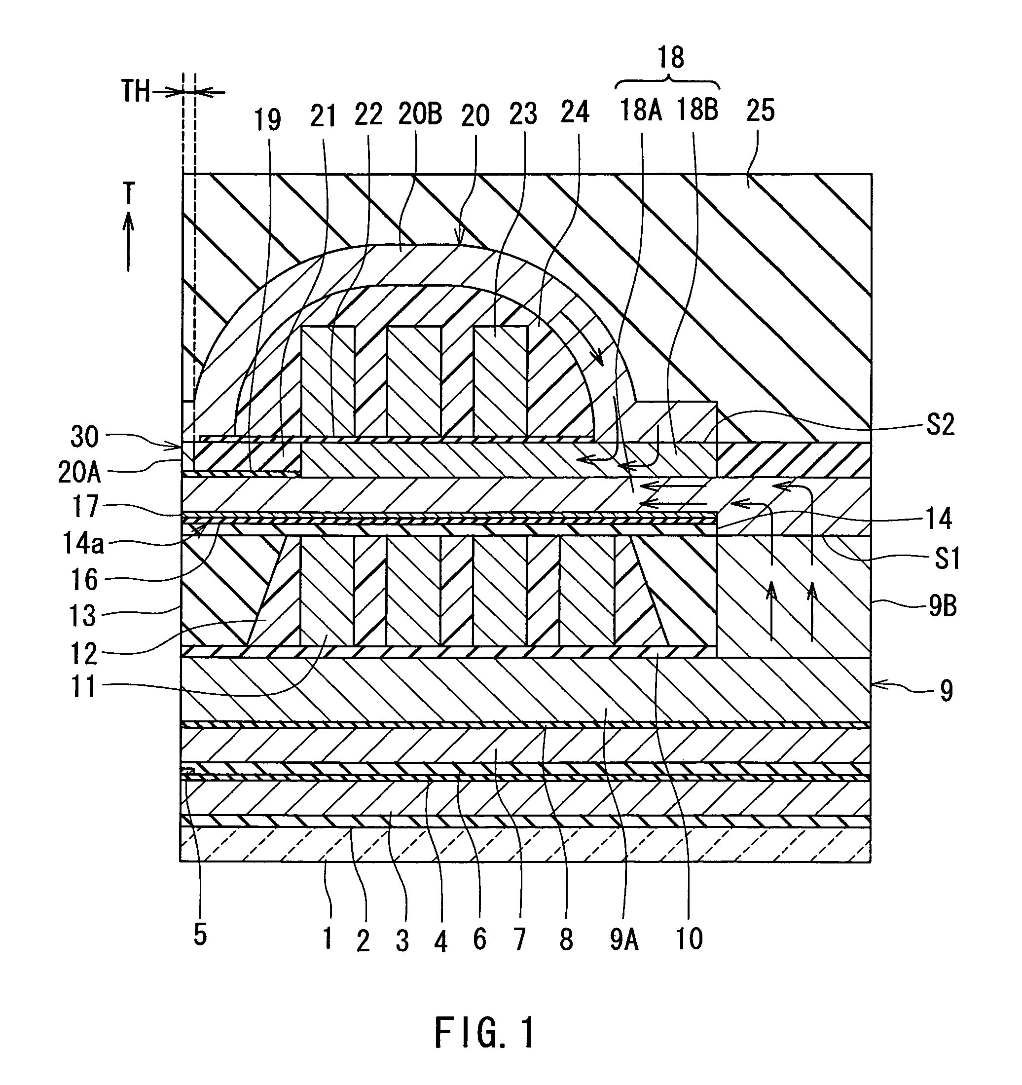
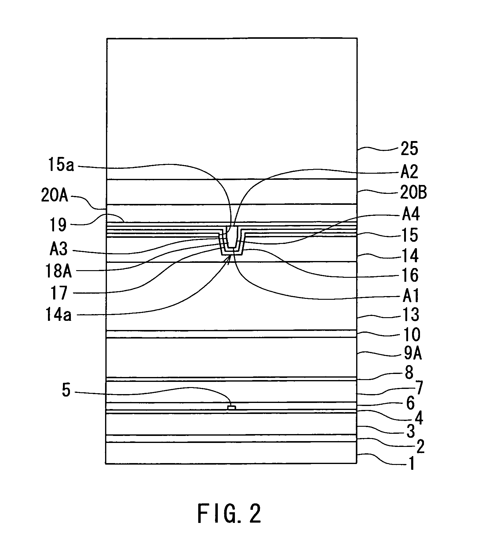
Preferred embodiments of the invention will now be described in detail with reference to the accompanying drawings. Reference is now made to FIG. 1 to FIG. 3 to describe the configuration of a magnetic head for perpendicular magnetic recording of a first embodiment of the invention. FIG. 1 is a cross-sectional view for illustrating the configuration of the magnetic head of the embodiment. FIG. 1 illustrates a cross section orthogonal to the medium facing surface and the plane of a substrate. The arrow indicated with T in FIG. 1 shows the direction of travel of a recording medium. The arrow with T denotes the same in the other drawings, too. FIG. 2 is a front view of the medium facing surface of the magnetic head of the embodiment. FIG. 3 is a top view of a pole layer of the magnetic head of the embodiment.
As shown in FIG. 1 and FIG. 2, the magnetic head for perpendicular magnetic recording (hereinafter simply called the magnetic head) of the embodiment comprises: a substrate 1 made ...
second embodiment
Reference is now made to FIG. 12 to describe a magnetic head of a second embodiment of the invention. FIG. 12 is a cross-sectional view for illustrating the configuration of the magnetic head of the second embodiment. FIG. 12 illustrates a cross section orthogonal to the medium facing surface and the plane of the substrate.
In the magnetic head of the second embodiment, the insulating layer 13 is provided to cover the first coil 11 and the insulating layer 12. The insulating layer 13 and the second layer 9B have flattened top surfaces.
In the second embodiment a lower yoke layer 18C is provided in place of the upper yoke layer 18B of the first embodiment. The magnetic layer 18 for writing of the second embodiment incorporates the pole layer 18A and the lower yoke layer 18C. The lower yoke layer 18C is connected to the pole layer 18A and disposed backward of the pole layer 18A along the direction T of travel of the recording medium at a location away from the medium facing surface 30. ...
third embodiment
Reference is now made to FIG. 13 to FIG. 15 to describe a magnetic head of a third embodiment of the invention and a method of manufacturing the same. Each of FIG. 13 to FIG. 15 is a cross-sectional view for illustrating the configuration of the magnetic head of the third embodiment. Each of FIG. 13 to FIG. 15 illustrates a cross section orthogonal to the medium facing surface and the plane of the substrate.
The magnetic head of the third embodiment is similar to the magnetic head of the first embodiment but has differences as will now be described. In the magnetic head of the third embodiment, when seen in the direction orthogonal to the interface S2 between the second layer 20B and the upper yoke layer 18B, at least part of the interface S2 is disposed at a location that coincides with at least part of the interface S1 between the second layer 9B and the pole layer 18A. The magnetic head of the third embodiment has a nonmagnetic layer 28B made of a nonmagnetic material and disposed...
PUM
| Property | Measurement | Unit |
|---|---|---|
| height | aaaaa | aaaaa |
| thickness | aaaaa | aaaaa |
| thickness | aaaaa | aaaaa |
Abstract
Description
Claims
Application Information
 - R&D
- Intellectual Property
- Life Sciences
- Materials
- Tech Scout
- Unparalleled Data Quality
- Higher Quality Content
- 60% Fewer Hallucinations
Browse by: Latest US Patents, China's latest patents, Technical Efficacy Thesaurus, Application Domain, Technology Topic, Popular Technical Reports.
© 2025 PatSnap. All rights reserved.Legal|Privacy policy|Modern Slavery Act Transparency Statement|Sitemap|About US| Contact US: help@patsnap.com


