Communicating road noise control system, in-vehicle road noise controller, and server

a technology of communication road noise and control system, which is applied in the field of communication road noise control system, can solve the problems of large memory required to store noise spectrum patterns, inability to implement noise control in the apparatus independently, and the amount of storable noise spectrum patterns is limited to the available storage space and the size of noise spectrum patterns, so as to improve the phonetic recognition rate

Inactive Publication Date: 2011-05-10
DENSO CORP
View PDF5 Cites 60 Cited by
  • Summary
  • Abstract
  • Description
  • Claims
  • Application Information

AI Technical Summary

Problems solved by technology

Therefore, the noise control in the apparatus cannot be implemented independently, that is, without detecting the present position of the vehicle.
Therefore, a very large memory is required to store noise spectrum patterns.
Further, the amount of storable noise spectrum patterns is thereby limited to the available storage space and the size of the noise spectrum patterns.

Method used


Image

  • Communicating road noise control system, in-vehicle road noise controller, and server
  • Communicating road noise control system, in-vehicle road noise controller, and server
  • Communicating road noise control system, in-vehicle road noise controller, and server

Examples


first embodiment

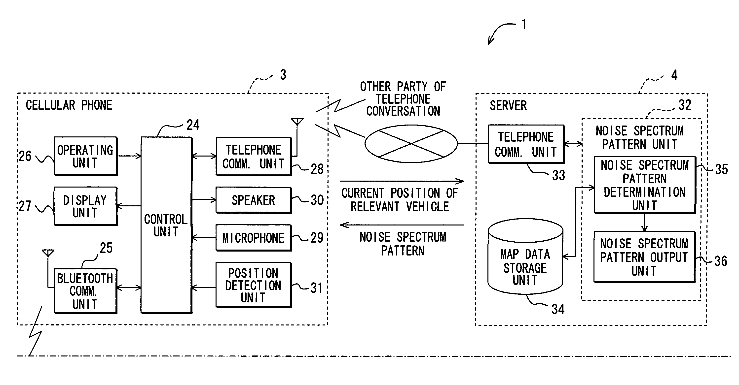
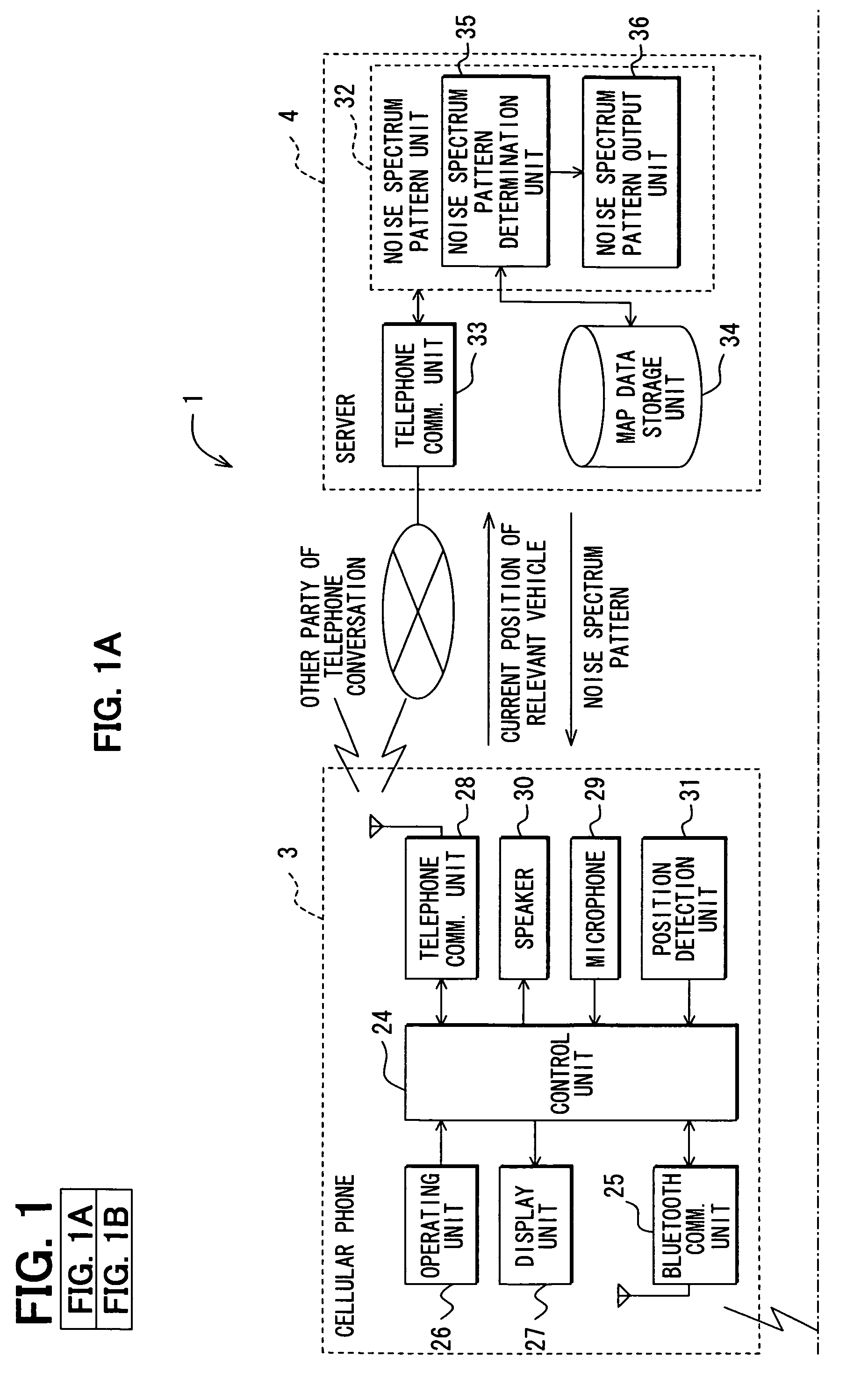
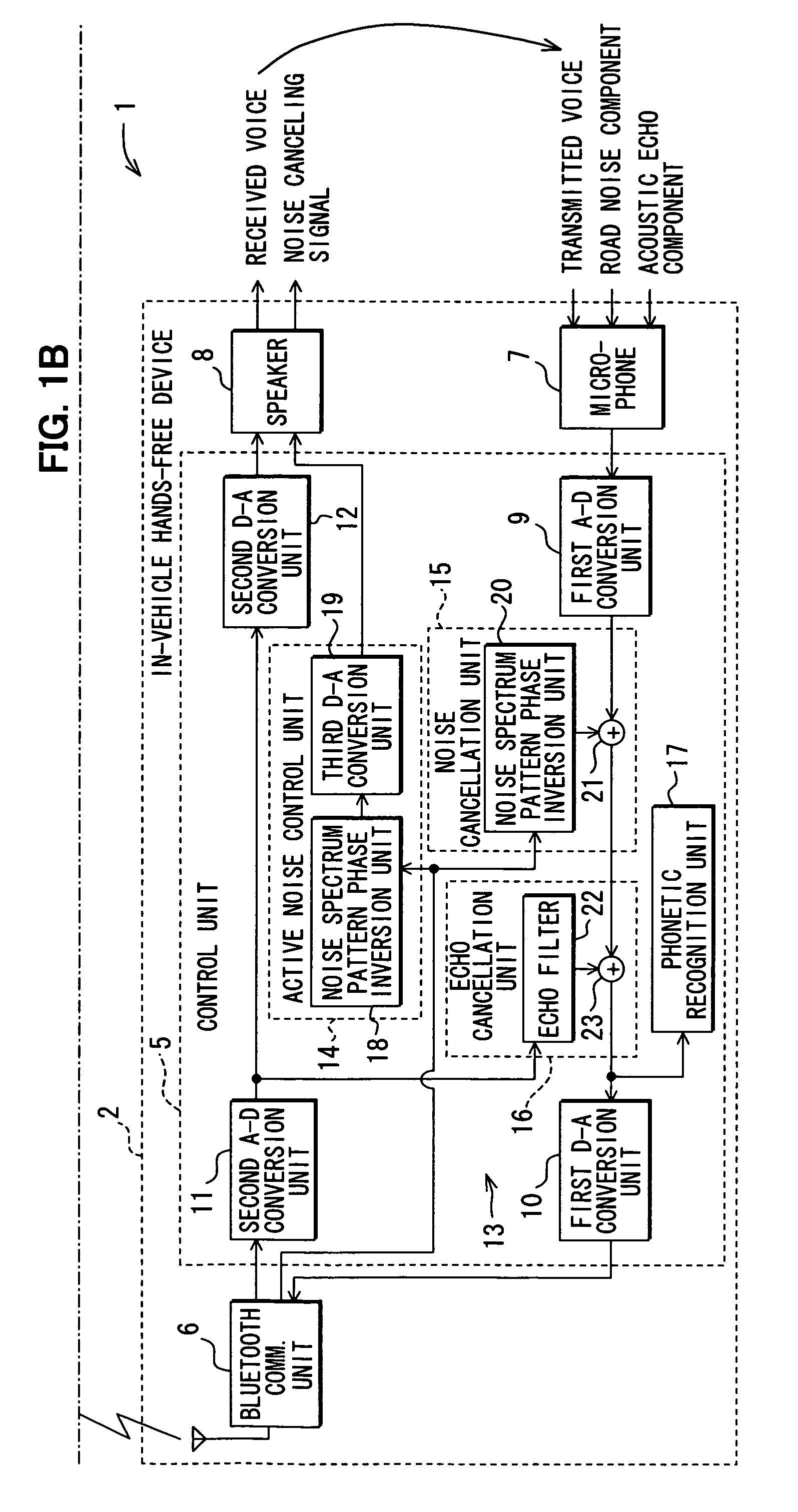
[0039]Hereafter, description will be given to a first embodiment of the invention with reference to FIG. 1 and FIG. 2. FIG. 1 illustrates the overall configuration of a communicating road noise control system in the form of functional block diagram. In accordance with the communicating road noise control system 1, an in-vehicle hands-free device 2 and a cellular phone 3 can communicate with each other via, for example, a Bluetooth® or similar short range or proximity-based protocol; and the cellular phone 3 and the server 4 can communicate with each other in a wide area via a wide area network. It should be noted that the in-vehicle hands-free device can refer to and include the in-vehicle road noise controller and the cellular phone can refer to telephone means and external device in accordance with the invention as described herein.

[0040]The in-vehicle hands-free device 2 can include a control unit 5 for carrying out for example, present position detection and acting as the transm...

second embodiment

[0061]Description will now be given to a second embodiment of the invention with reference to FIG. 3. It should be noted that description of the same members as in the first embodiment will be omitted for simplicity, and the description will be focused on the differences.

[0062]As described herein above, in accordance with the first embodiment, the present position of the vehicle is detected by the cellular phone 3, multiple different noise spectrum patterns corresponding to multiple different road surfaces are stored in the server 4, and of the multiple different noise spectrum patterns, a noise spectrum pattern corresponding to the road surface on which the vehicle is presently running is determined by the server 4. Meanwhile, in accordance with the second embodiment, the in-vehicle hands-free device detects the present position of the vehicle and transmits it to the server 4.

[0063]In a communicating road noise control system 41, an in-vehicle hands-free device 42 and a cellular ph...

third embodiment

[0067]Description will now be given to a third embodiment of the invention with reference to FIG. 4. The description of the same members as in the first embodiment will be omitted, and description will be focused on the differences. In accordance with a third embodiment, the in-vehicle hands-free device acquires the present position of the vehicle from the cellular phone and determines a noise spectrum pattern.

[0068]In a communicating road noise control system 51, an in-vehicle hands-free device 52 and the cellular phone 3 can communicate with each other via, for example, a Bluetooth® protocol or other short range or proximity-based protocol. The in-vehicle hands-free device 52 includes a noise spectrum pattern unit 54, a noise spectrum pattern determination unit 55, a noise spectrum pattern output unit 56, and a map data storage unit 57 having the same functions as those of the noise spectrum pattern unit 32, noise spectrum pattern determination unit 35, noise spectrum pattern outp...


PUM


Abstract

Road noise is reduced without locally storing noise spectrum patterns for determination or without detecting the present position of a vehicle from the device. An in-vehicle hands-free device causes a cellular phone to detect the present position of the vehicle and transmit the position to a server. The server determines a noise spectrum pattern corresponding to the road surface on which the vehicle is presently running. The noise spectrum pattern is based on the present position of the vehicle received from the in-vehicle hands-free device and road information. The server transmits the noise spectrum pattern to the in-vehicle hands-free device whereupon a noise canceling signal is superimposed on a received signal. The noise canceling signal is based on an inverted noise spectrum pattern that is obtained by inverting the phase of the noise spectrum pattern. The resulting composite signal is output from a speaker.

Description

CROSS REFERENCE TO RELATED APPLICATIONS[0001]The present invention is based on and claims priority to Unpublished Japanese Patent Application No. 2007-027959 filed on Feb. 7, 2007 and Unpublished Japanese Patent Application No. 2007-305898 filed on Nov. 27, 2007, the contents of both of which are incorporated in their entirety herein.BACKGROUND OF THE INVENTION[0002]1. Field of the Invention[0003]The present invention is related to a road noise control system, and more specifically to an in-vehicle road noise controller and a server communicating through a communication network.[0004]2. Description of Related Art[0005]Various technologies have been developed to facilitate an environment for a hands-free telephone conversation carried out in a vehicle compartment. One technology involves determining a noise spectrum pattern corresponding to the road surface on which a vehicle is presently running based on the present position of the vehicle and road information. The determined noise ...

Claims


Application Information

Patent Timeline
Patent Type & Authority Patents(United States)
IPC IPC(8): H04M1/00
CPCG10K11/1788H04R3/007H04M1/6075G10L21/0208G10K2210/12821G10L21/0216G10K11/17821G10K11/17857G10K11/17883G10K11/17885
Inventor MIYAUCHI, HIDEO
Owner DENSO CORP
Why Eureka
Try Eureka