Method and apparatus for a fan noise controller

Inactive Publication Date: 2001-06-12
MCDONNELL DOUGLAS
View PDF6 Cites 54 Cited by
  • Summary
  • Abstract
  • Description
  • Claims
  • Application Information

AI Technical Summary

Problems solved by technology

Despite the improvement over conventional turbojets, however, turbofan engines still produce a powerful roar.
Compliance with these regulations often presents an enormous expense to aircraft owners because engines or even entire aircraft may require replacement.
In some cases, compliance may even be impossible.
Current solutions for reducing engine noise have met with limited success.
Although a turbofan produces less jet noise than a turbojet, the fan itself has become a source of considerable noise.
Much of the fan noise may be produced by interaction between unsteady fluid flows and solid surfaces.
In addition, as fans become larger and more powerful, the contribution of the fan to the overall noise of the engine becomes more pronounced.
Under high loading conditions, the most significant of such disturbances to the flow downstream are caused by the development of blade leading edge vortices and stronger blade tip vortex shedding.
Consequently, fan blade

Method used


Image

  • Method and apparatus for a fan noise controller
  • Method and apparatus for a fan noise controller
  • Method and apparatus for a fan noise controller

Examples


Embodiment Construction

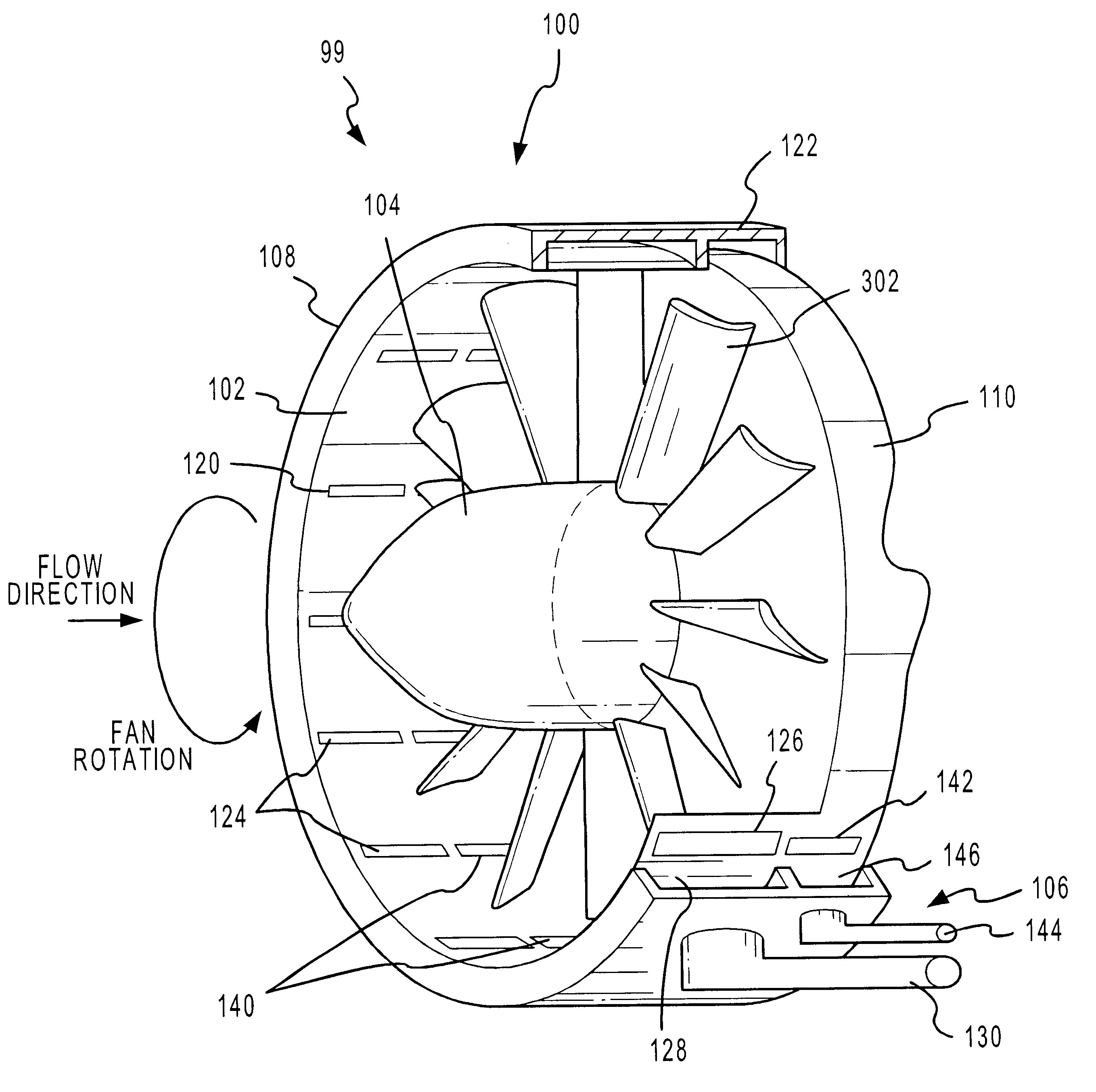
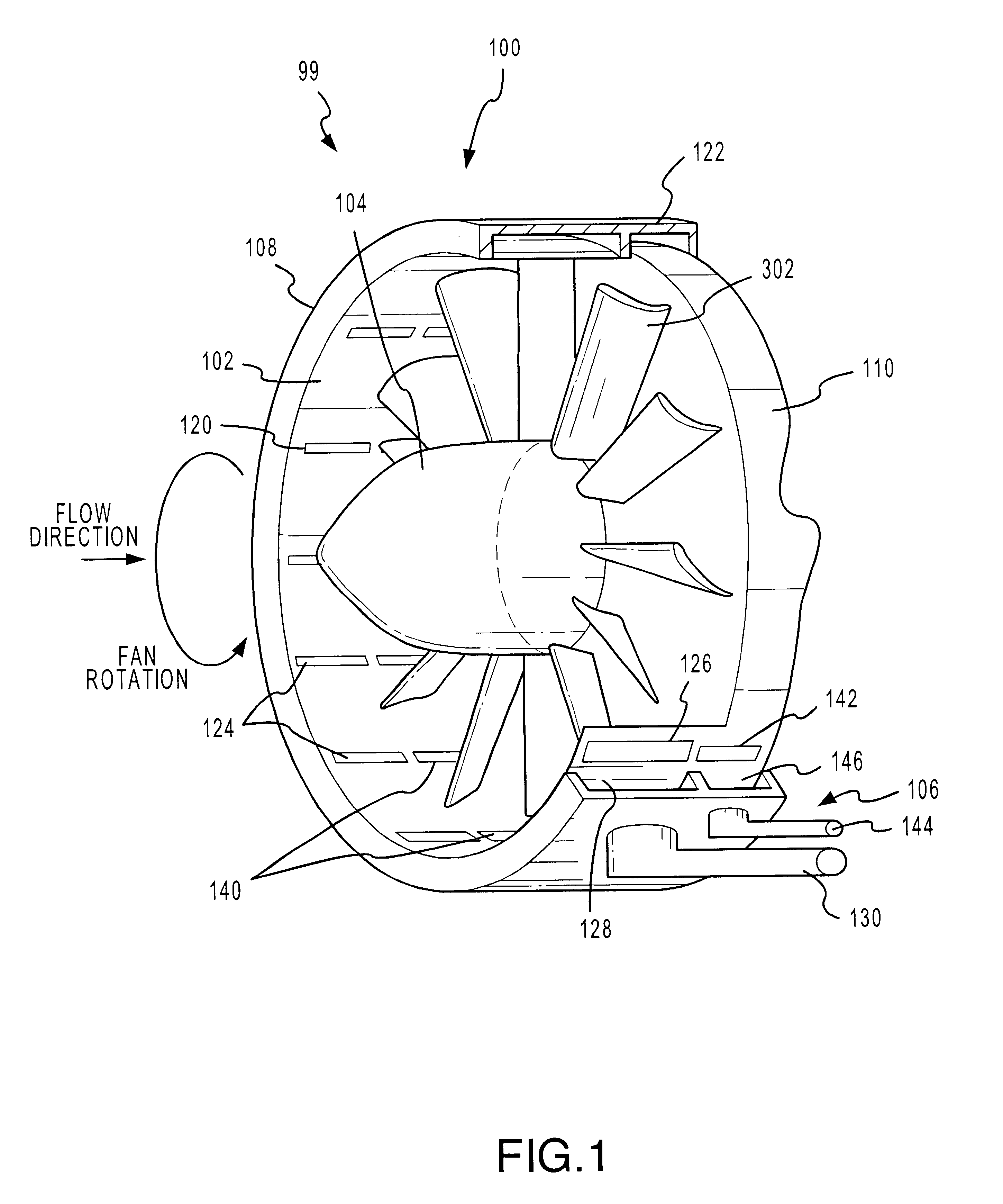
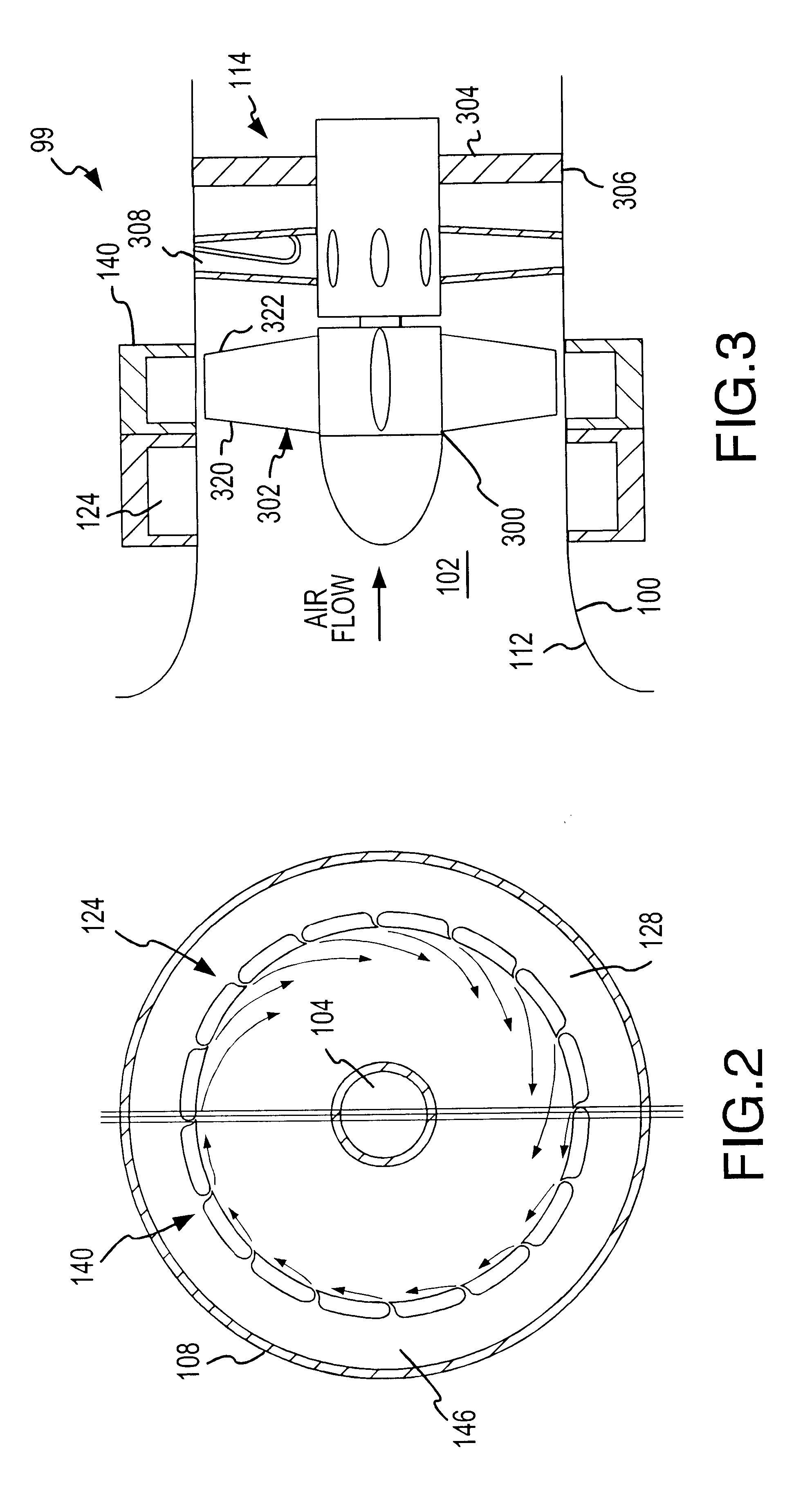
Referring now to FIGS. 1 and 3, a fan system 99 according to various aspects of the present invention suitably comprises: a housing 100 having a fluid flow channel 102; a power plant (not shown); a fan assembly 104; and a fan noise control system 106. The present embodiment is described in conjunction with an aircraft turbofan system, though various aspects of the present invention may be used in conjunction with any system having rotating blades including, for example, commercial cooling fans, marine propulsion systems, blow dryers, and the like. In particular, the housing 100 suitably defines the fluid flow channel 102 in which the fan assembly 104 is disposed. Various components of the fan assembly 104 suitably rotate within the fluid flow channel 102, and the fan assembly 104 is suitably coupled to the power plant. The power plant provides power to rotate the fan within the housing 100.

The fan assembly 104 suitably comprises any apparatus having rotating blades. In the present e...


PUM


Abstract

A fan system, such as a turbofan, marine propeller, or a cooling fan, includes a fan noise control system for reducing noise generated by the fan system. The noise control system may be configured to reduce either broadband noise, blade-passage noise, or both. In particular, the fan noise control system suitably includes a pre-swirl generator configured to provide a layer of fluid upstream from the fan blades. The layer swirls in the direction of the fan's rotation, reducing the angular velocity differential between the fan blades and the incident fluid. In addition, the fan noise control system may also include a fluid seal generator configured to create a fluid barrier between the fan blade tips and the interior surface of the fluid flow channel. The fluid seal inhibits leakage flow between the fan blade tips and the interior surface as well as the formation of blade vortices. By minimizing the blade wake and the blade tip vortices without adding solid surfaces, noise tends to diminish.

Description

1. Field of the InventionThe present invention generally relates to noise control, and more particularly, to methods and apparatuses for controlling noise and vibrations generated by rotating blades of a fan.2. Background of InventionVirtually all large modern transport aircraft, especially civil aircraft, use turbofan engines. A turbofan engine essentially comprises a turbojet with a large low-pressure compressor, in which airflow is discharged as a relatively cool and slow propulsive jet. The turbofan exhibits superior propulsive efficiency and fuel consumption characteristics over ordinary turbojets. Perhaps the most important advantage of turbofan engines over turbojets in civil aviation, however, is the dramatically lower noise level.Despite the improvement over conventional turbojets, however, turbofan engines still produce a powerful roar. The sound of turbofan engines continues to generate animosity among the public towards the aviation industry. Noise concerns produce resis...

Claims


Application Information

Patent Timeline
IPC IPC(8): B63H1/18B64C11/00B63H1/16B63H1/28B63H1/00F01D11/10F01D11/08F01D5/14G10K11/16G10K11/00
CPCB63H1/16B63H1/18B63H1/28B64C11/001F01D5/141F01D11/10G10K11/161Y02T50/672Y02T50/673F05D2260/96Y10S415/914Y02T50/60
Inventor NGO, HIEU THIEN
Owner MCDONNELL DOUGLAS
Why Eureka
Try Eureka