Active noise reduction audiometric headphones

a technology of active noise reduction and headphones, applied in the field of audiometry, can solve the problems of not using specific switching circuitry or using noise attenuation circuitry in the prior art, and achieve the effects of reducing the volume of the cavity, reducing the passive performance of the cushion, and no air gaps

Inactive Publication Date: 2003-03-11
GENTEX CORP
View PDF6 Cites 55 Cited by
  • Summary
  • Abstract
  • Description
  • Claims
  • Application Information

AI Technical Summary

Benefits of technology

The ANR audiometry headphones can be designed in such a way that this standardized calibration procedure can be adhered to without costly changes or modifications in standards. FIG. 6 illustrates this standard calibration process for one embodiment of the ANR audiometry headphone. The earphone (52) and cushion (53) styles shown are meant to depict the standard TDH type speaker coupled with the MX style cushion. This permits a calibration procedure that adheres to the standard, specifying a type 9-A acoustic coupler (56) creating a 6 cc volume (55) with a one inch microphone (57). The ANR audiometry headphone must include an acousto-electric transducer (54) to measure the noise under the earcup during operation. Typically this is a microphone that can be quite small. In FIG. 6, the microphone is shown as being integrated into the MX style cushion. This detail is critical in that the presence of the microphone does not reduce the volume of the cavity created during the calibration procedure. It is also important that the microphone be molded into the cushion so that no air gaps or leaks will reduce the passive performance of the cushion. Molding the electro-acoustic sensor into the ear cushion is only one of many possible arrangements that will permit the current calibration standard to be adhered to. The speaker could be slightly recessed inside its casing (52) to provide room for the microphone. This is a more significant design change, but one that would also meet the specification for calibration.
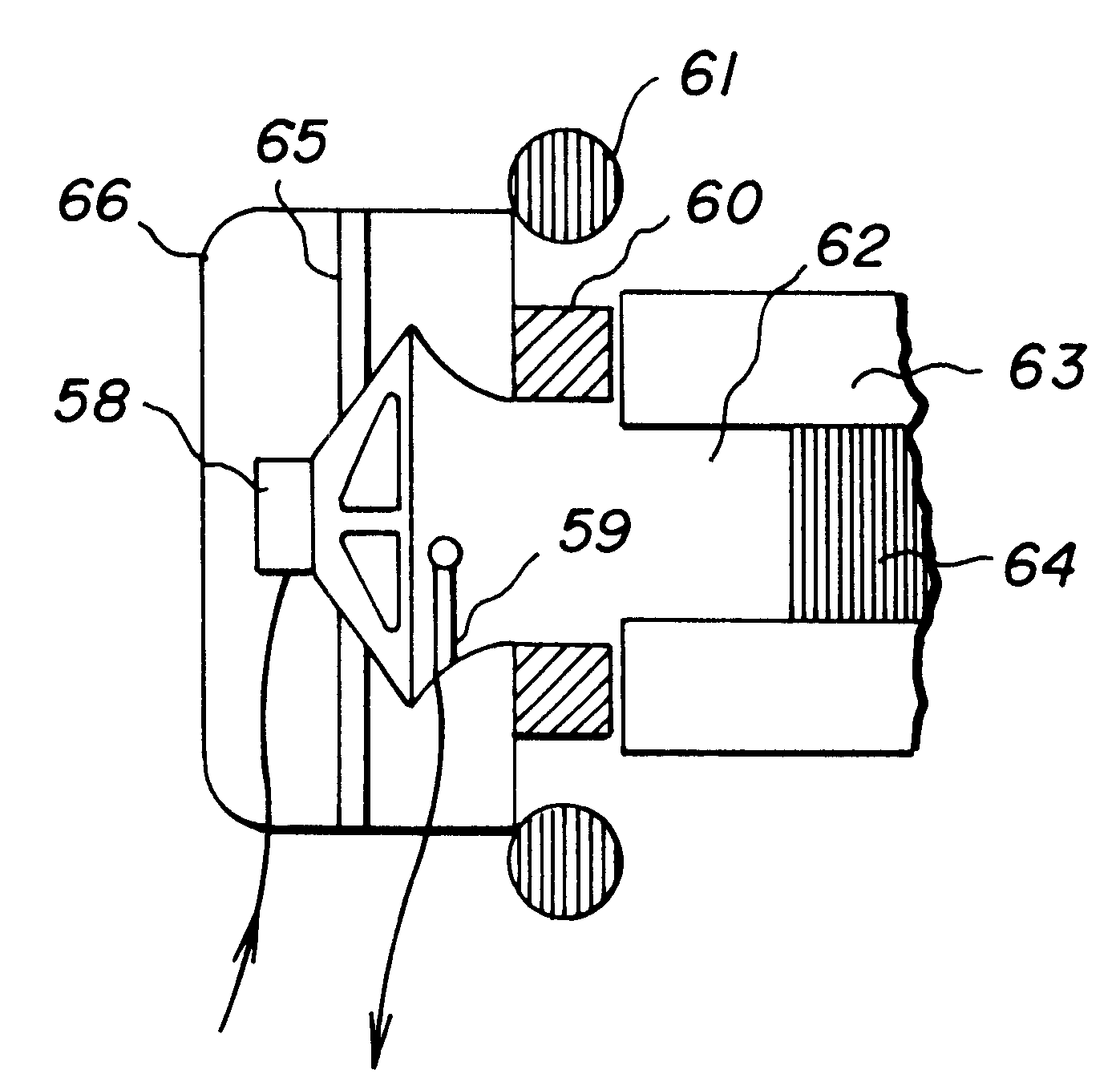
As mentioned earlier, the TDH style speaker is not particularly well suited for active noise control due to its poor low frequency response. For this reason it is very important to consider other possible alternatives, whether they meet the current specification for audiometers or not. FIG. 7 illustrates only one of these possible alternatives for actuator, sensor, and passive control configurations. Although not drawn to scale, it is clear from the above description and FIG. 6, that this design will not meet the current specification for calibration of earphones. The speaker (58) is mounted as at (65) inside a circumaural cup (66) that contacts the subject's head at the cushion (61). A second inner cushion (60) will contact the user's pinna first, ensuring a seal with a known average volume and improving passive performance.
In this arrangement, the acousto-electric sensor can be more freely located in front of the speaker or closer to the user's ear canal. For each ANR audiometry headphone system design there is an optimum position for this sensor that offers the best perceived performance. The control performance is better when the microphone is closer to the speaker because of the reduced time delay. But as frequencies increase, the zone of silence around the sensor becomes smaller and the subject will have difficulty perceiving the effects without moving the microphone closer to the eardrum. One final criteria for the positioning of the sensor in the ANR audiometry headphone relates to the variability of the system dynamics for different test subjects. It is desirable to minimize this variability as it can adversely affect fixed gain control performance. Testing has shown that larger volumes (62) between the speaker and the pinna (where the sensor resides) provide less variability among users. Recall that the calibration standard requires a 6 cc volume that approximates the average volume present when the TDH and MX pair are placed on the subject's ear with a 4.5 N force headband. Better ANR performance can be achieved for a wider spectrum of the population if this volume is increased. This will clearly require a new calibration standard. While it is not the purpose of this embodiment to provide a completely new standard, it is intended to provide for a means by which this new standard can be created for a variety of ANR audiometry headphones.

Problems solved by technology

It is noteworthy that none of the prior art discloses the use of noise attenuation circuitry in audiometry or the use of the specific switching circuitry disclosed herein.

Method used


Image

  • Active noise reduction audiometric headphones
  • Active noise reduction audiometric headphones
  • Active noise reduction audiometric headphones

Examples


Embodiment Construction

Advances in digital signal processing and knowledge of local and global noise control approaches have caused active noise control (ANR) to take a more prominent stance in state-of-the-art technology. Specifically, active noise reduction (ANR) headphones have become commonplace technology for the purpose of hearing protection. Low frequency disturbing noise is the easiest target for ANR headphones because the zone of silence for low frequencies is quite large and the passive control provided by the circumaural cups housing the ANR actuator, is ineffective for low frequencies.

Low frequency noise disturbances are also a problem in audiometry testing. ANSI and OSHA requirements for ambient noise in the vicinity of audiometry testing are quite stringent, the reason being that the threshold for hearing can shift upward due to the presence of ambient noise in the test environment. This is of primary concern for individuals who must pass hearing tests in order to continue working, as well a...


PUM


Abstract

Active noise reduction headphones for audiometry where the earphone portion of said headphones has a cavity volume greater than 6 cc and including an acoustic-electric sensing means and an electro-acoustic transducing means which are used cooperatively and which has additional passive noise control means in the form of a circumaural seal around the ear for improving high frequency noise control performance, the headphone having a summing junction for combining the active noise reduction signal and an audiometry test signal.

Description

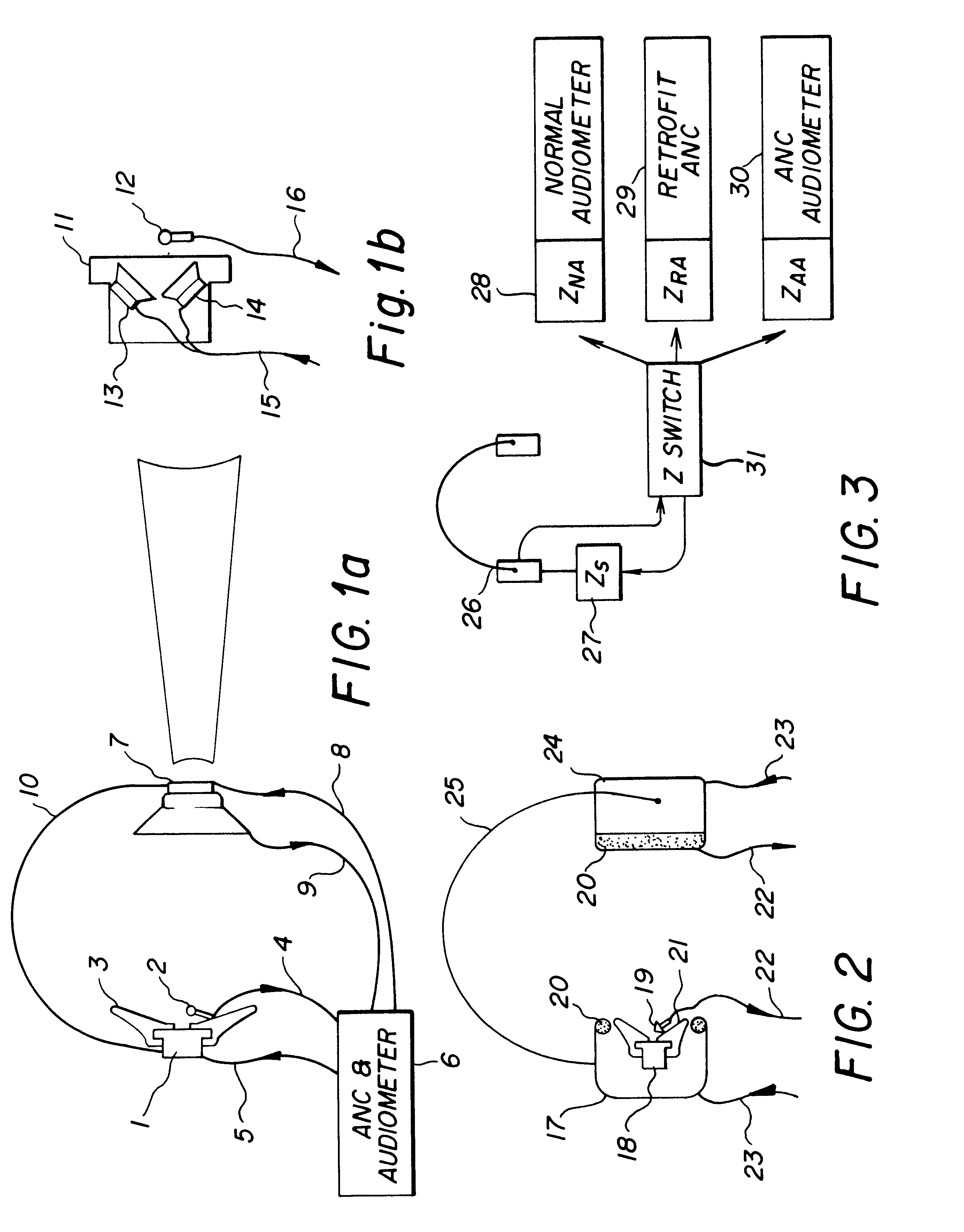
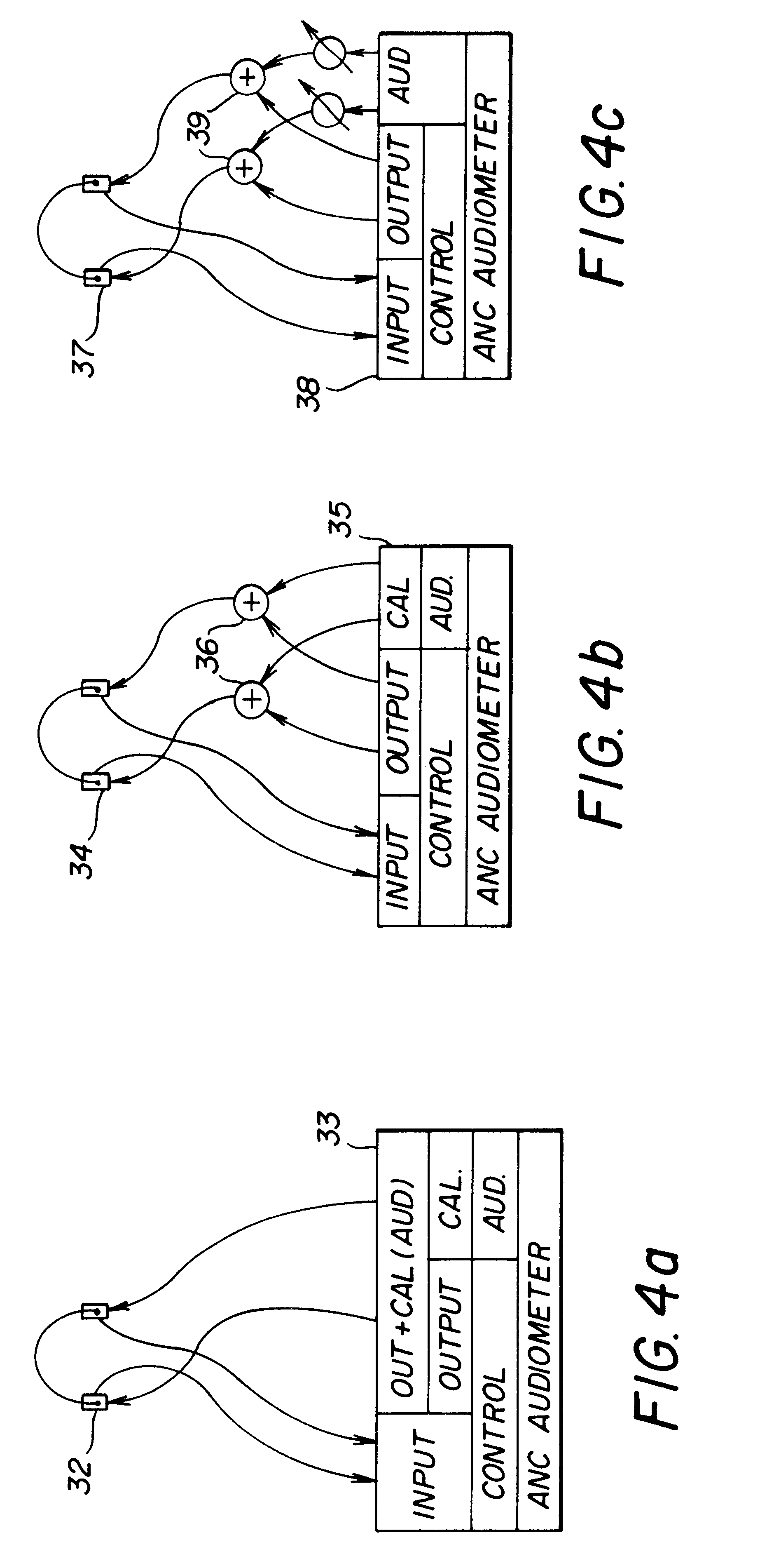
This invention relates to the use of an audiometry headphone system utilizing an acousto-electric transducer for the purpose of implementing active noise control during and in conjunction with audiometry testing. Since the process of some embodiments of active noise control alter the audiometry test stimulus, methods for correcting that alteration are also covered. Details of the inventions include passive control measures used in conjunction with ANR audiometer headphones, calibration procedures, and ANR headphone design provisions for alternative ANR audiometer configurations. The invention also describes several new and unique methods for calibrating both standard and ANR audiometry headphones. A calibration process which occurs external to the audiometer and that is integrated into the headphone or the headphone wiring mechanism will operate with a standard headphone or a special configuration of the ANR audiometer headphone. An alternative manual or automatic calibration proced...

Claims


Application Information

Patent Timeline
Patent Type & Authority Patents(United States)
IPC IPC(8): G10K11/178G10K11/00H04R29/00A61B5/12H04S1/00
CPCG10K11/1788H04S1/005H04R1/1083A61B5/12G10K2210/116G10K2210/1081G10K11/17854G10K11/17861G10K11/17875G10K11/17885
Inventor VAUDREY, MICHAEL ALLENSAUNDERS, WILLIAM RICHARD
Owner GENTEX CORP
Why Eureka
Try Eureka