Clamping device

a technology of a clamping device and a clamping bore, which is applied in the direction of tyre repairing, tyre parts, structural/machine measurement, etc., can solve the problems of increasing the effort needed to pull the bolt out of the centering bore, requiring a corresponding amount of effort, and unable to achieve the effect of high component strength

Inactive Publication Date: 2011-05-17
HAWEKA
View PDF16 Cites 3 Cited by
  • Summary
  • Abstract
  • Description
  • Claims
  • Application Information

AI Technical Summary

Benefits of technology

[0009]It is the object of the present invention to provide a clamping device of the type mentioned at the beginning which makes it possible, in a simple manner, for the centering bolts to be fastened to the clamping flange and for the centering bolts to be released later from the clamping flange, with a centered arrangement of the centering bolts in the recesses being ensured even after a relatively long period of use of the clamping device. Furthermore, the clamping device according to the invention is to be distinguished by a high component strength.
[0011]In the invention, neither the centering bolt in the insertion region nor the recesses in the clamping flange have a circular contour. Instead, the contours are selected in such a manner that the circumferential surface of the centering bolt in the insertion region and the adjacent circumferential surface of the side wall of the clamping flange in the region of the recess are designed as interacting run-on surfaces or run-on slopes which, by rotation of the centering bolt about the longitudinal axis thereof, enter into mutual engagement and ensure a frictional connection, which acts in the axial and circumferential directions, between the centering bolt and the clamping flange after a predetermined angle of rotation has been reached. The frictional connection applies a sufficiently large holding force which, upon highly precise centering, fixes the centering bolt within the recess on the clamping flange. It is nevertheless possible, by simple rotating back with little effort, to release the frictional connection again and remove the centering bolt from the recess. Furthermore, the fixing of the centering bolt on the clamping flange by means of interacting run-on surfaces or run-on slopes is structurally simple and does not result in a weakening of the component strength of the centering bolt and / or of the clamping flange.
[0012]Furthermore, the profile contour of the centering bolt in the insertion region and the profile contour of the recess are matched to each other in such a manner that, when the centering bolt is inserted and subsequently rotated into a closure position, the centering bolt is automatically centered in the recess. As a result, the centered arrangement of the centering bolt in a recess is ensured without the centering bolt having to be adjusted manually.
[0014]In order to ensure a satisfactory function over a relatively long period of use in spite of the increasing wear of those surface portions of the centering bolt and of the clamping flange which participate in the formation of a frictional connection, the profile contour of the centering bolt in the insertion region and the inner contour of the side wall of the clamping flange in the region of the recess are preferably designed in a manner such that they are complementary to each other such that the angle of rotation of the centering bolt in the recess required in order to form a frictional connection is dependent on the state of wear of the surface portions forming the frictional connection between the bolt and clamping flange. The required angle of rotation about which the centering bolt has to be rotated in the recess in order to be able to enter into a frictional connection with the clamping flange is predetermined by the complementary contours. Due to wear, the surfaces of the centering bolt and / or of the clamping flange become worn down, the increasing abrasion causing the centering bolt to have to be rotated more powerfully in order to form a frictional connection between the centering bolt and the clamping flange. The angle of rotation of the centering bolt in a new state of the clamping device should preferably correspond to approximately half the maximum possible angle of rotation for forming a frictional connection in a state of wear of the clamping device. As a result, despite increasing wear, the formation of a frictional connection can be ensured, it being necessary, depending on the corresponding wear of the contact surfaces, to rotate the centering bolt about an angle which is greater than the maximum possible angle of rotation in the new state.
[0016]In a preferred embodiment, the distance between the center point of the recess and the inner contour of the side wall of the clamping flange decreases continuously in a circumferential direction over the length of an arc portion from a starting point on the inner contour with a greatest distance from the center point of the recess in the region of a beginning of an arc as far as an end point on the inner contour with a smallest distance from the center point of the recess in the region of an end of the arc. When the centering bolt is inserted into a recess, a relative movement between the centering bolt and the clamping flange is therefore possible in the recess. When the centering bolt is rotated in the one circumferential direction, the play existing between the centering bolt and the clamping flange decreases until a frictional connection between at least one surface portion of a circumferential surface of the centering bolt and at least one adjacent surface portion of the side wall or inner wall of the clamping flange, which wall bounds the recess, occurs. For simplified insertion of the centering bolt into a recess, the distance between the center point of the recess and the inner contour can increase continuously from a beginning point of the arc portion in the direction of the starting point.
[0020]In another embodiment of the invention, the profile contour of the centering bolt in the insertion region has a plurality of arc portions following one another in the circumferential direction of the centering bolt, and the arc portions of the profile contour of the centering bolt are formed in a complementary manner to the arc portions of the inner contour of the side wall of the clamping flange in the region of the recess. This ensures a large contact surface between the centering bolt and the clamping flange in the region of the recess in the frictional connection position, which contributes to a correspondingly low surface pressure and therefore to low wear.

Problems solved by technology

A disadvantage in this case is that some of the centering bolts can only be inserted into the centering bores with a considerable amount of effort.
In order to pull the bolt out, it then has to be pulled out of the bore counter to the holding force of the rubber ring, which in turn requires a corresponding amount of effort.
If the bolts are not moved for a relatively long period of time, the centering bolts may furthermore become stuck in the centering bores, which results in an increased effort being needed to pull the bolts out of the centering bores.
A securing ring also prevents the release here of the bolt from the clamping flange, which results in the above-described disadvantages.
Furthermore, the deformation of the circumference of the centering bolt is structurally complicated and associated with high production costs.
The insertion region of the centering bolt is also drilled to be hollow, thus significantly reducing the component strength of the centering bolts.

Method used


Image

  • Clamping device
  • Clamping device
  • Clamping device

Examples


Embodiment Construction

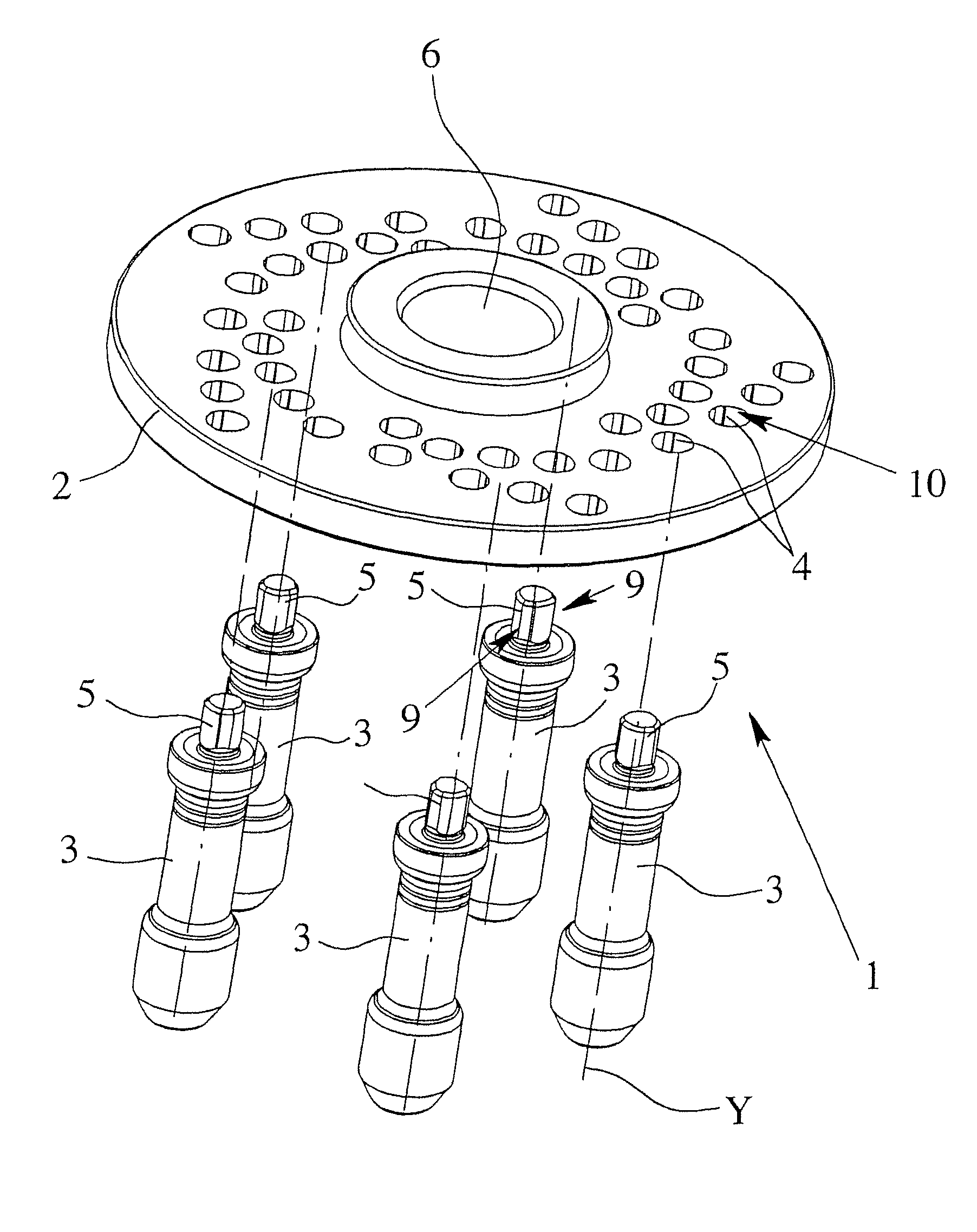
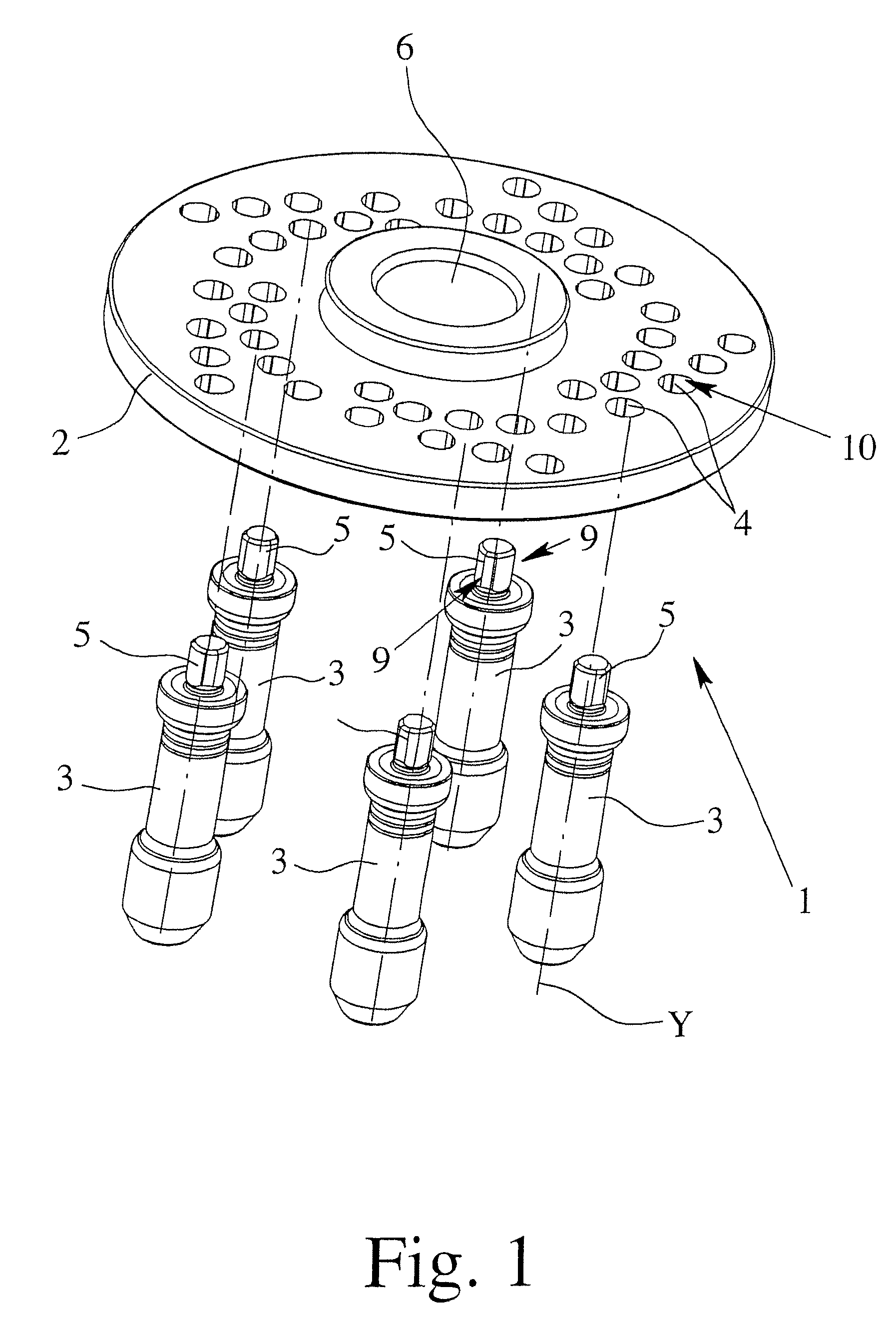
[0033]FIG. 1 illustrates a clamping device 1 for clamping a vehicle wheel (not illustrated) onto a shaft of a wheel balancing machine, said clamping device having a clamping flange 2 and a plurality of centering bolts 3. The clamping flange 2 has a plurality of recesses 4 for receiving the centering bolts 3, a centering bolt 3 being releasably insertable by means of an insertion region 5 into a recess 4. The centering bolts 3 are fixed releasably into a group of recesses 4 corresponding to the arrangement of holes in the rim of the vehicle wheel to be clamped. The vehicle wheel is centered radially during the wheel balancing operation by means of the centering bolts 3 which engage in the centering or fastening holes of the rim of the vehicle wheel. The clamping flange 2 has a central aperture 6 which makes it possible to push said clamping flange onto the shaft of the wheel balancing machine.

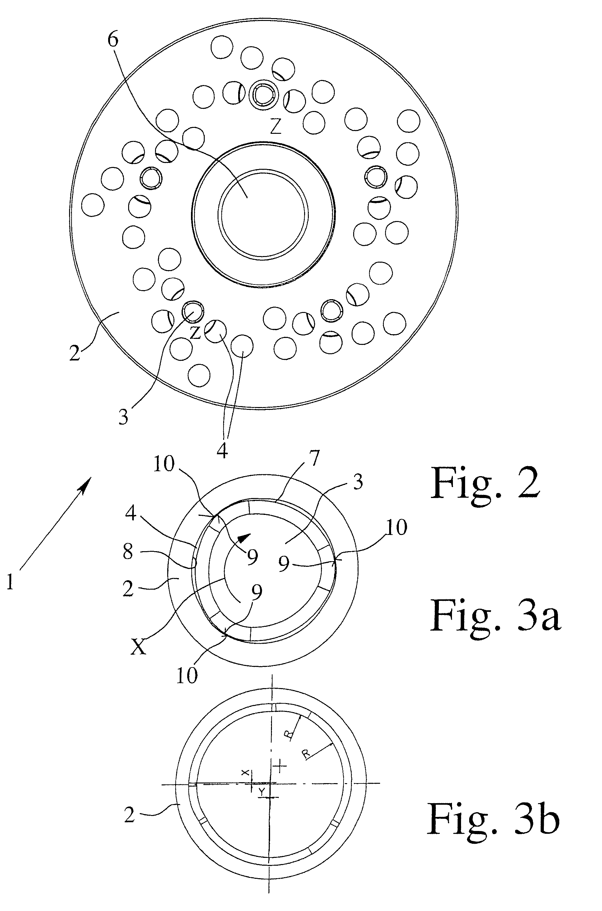
[0034]FIG. 2 illustrates a view from below of the clamping device 1 illustrated in FIG. 1, t...


PUM


Abstract

A clamping device for mounting a vehicle wheel on a balancing machine. The clamping device has a clamping flange and a plurality of centering bolts. The clamping flange is provided with plural sets of recesses for the centering bolts. An insertable section of each centering bolt is removably insertable into a recess. A profiled contour in the insertable section of the centering bolt and an inner contour of a sidewall of the clamping flange delimiting the recess are not circular and have complementary shapes such that the centering bolt is accommodated in the recess such that some sections of the centering bolt can be rotated about the longitudinal axis thereof. When the centering bolt is rotated, at least one subarea of a circumferential surface in the insertable section of the centering bolt frictionally engages with at least one adjacent subarea of the sidewall of the clamping flange delimiting the recess.

Description

BACKGROUND OF THE INVENTION[0001]1. Field of Invention[0002]The invention relates to a clamping device for clamping a vehicle wheel onto a shaft of a wheel balancing machine, with a clamping flange and with a plurality of centering bolts, wherein the clamping flange has a plurality of recesses for receiving the centering bolts, and wherein each centering bolt can be inserted releasably by means of an insertion region into a recess. Furthermore, the present invention relates to a clamping flange and a centering bolt, each designed for use in a clamping device of the abovementioned type.[0003]2. Description of Related Art[0004]A clamping device of the abovementioned type is known, for example, from European Patent Application EP 0 738 885 A2 and corresponding U.S. Pat. No. 5,665,911 and serves to clamp wheels of different types of motor vehicles onto a shaft of a wheel balancing machine. The known clamping device has a central guide bore in the clamping flange for axially guiding the ...

Claims


Application Information

Patent Timeline
Patent Type & Authority Patents(United States)
IPC IPC(8): G01M1/04G01B5/255G01D21/00
CPCG01M1/045
Inventor WARKOTSCH, DIRK
Owner HAWEKA
Why Eureka
Try Eureka