Folding type cable protection and guide device

a guide device and cable protection technology, applied in the direction of cables, insulated conductors, relatively moving parts, etc., can solve the problems of large width and length, complicated structure and its attendant assembly, and achieve the effect of convenient adaptation, convenient assembly and satisfying the performance of the devi

Active Publication Date: 2011-05-17
TSUBAKIMOTO CHAIN CO
View PDF30 Cites 19 Cited by
  • Summary
  • Abstract
  • Description
  • Claims
  • Application Information

AI Technical Summary

Benefits of technology

[0018]A folding type cable protection and guide device is formed wherein a cable is accommodated into a rectangularly shaped cable accommodating space. The rectangularly shaped cable accommodating space is formed from a synthetic resin tape. The synthetic resin tape is extruded in a longitudinal direction. The cable accomodating space is shaped by folding a pair of right and left folded sections which are part of the synthetic resin tape. The accomodating space extends in a longitudinal direction of an extruded synthetic resin tape. Both linear movement and flexional movement can repeated for extended durations of time with satisfactory performance of the device. In order to protect and guide a long cable, the synthetic resin tape can be cut as an integrated object according to the length of the cable. As a result, the cable accommodating space can be easily adapted to the optimum length to accomodate the cable. Thus, assembly is simplified. Connecting a large number of link plates of a conventional protection and guide chain to each other for a specific cable length is not necessary.
[0019]According to an example of the invention, the synthetic resin film tape is continuously extruded irrespective of the length of a cable to be accommodated. A long device can be easily manufactured without the need for a metal mold. Extrusion molding does not require various sizes of metal molds as is the case of injection molding or casting in order to accommodate specific lengths of a cable.
[0020]According to an example of the invention, since the synthetic resin tape can be easily folded through a folding section, a rectangularly shaped cable accommodating space can be uniformly and reliably assembled in a desired length.
[0021]The synthetic resin tape has outer circumferential wall formation sections and a pair of right and left side wall formation sections. The outer circumferential wall formation sections adjacently engage each other in a longitudinal direction of the tape during linear movement. The outer circumferential wall formation sections separate from each other to open at predetermined pitches in the longitudinal direction of the tape during flexional movement. Smooth flexional movement can be attained with the outer circumferential wall formation sections and the pair of right and left side wall formation sections being respectively separated from each other with a flexional movement radius.
[0022]The synthetic resin tape has outer circumferential wall formation sections, a pair of right and left side wall formation sections, and a pair of right and left inner circumferential wall formation sections. The pair of right and left inner circumferential wall sections are integral with the pair of right and left side wall formation sections.
[0023]When assembled, the pair of right and left inner circumferential wall sections are on one side of the cable accomodating space opposite the outer circumferential wall formation sections. The pair of right and left inner circumferential wall sections come together in an overlapped manner along the longitudinal direction of the tape during assembly. During both linear movement and flexional movement, the synthetic resin tape naturally maintains a rectangular section-shaped cable accommodating space once folded through folding sections. As a result, both the linear movement and the flexional movement can be smoothly repeated for a long period of time.

Problems solved by technology

Problems arise from the complicated structure and its attendant assembly.
Further, when a foldable protection element described in Japanese Patent Indication No. 2001-514725 is injection-molded or cast in one piece and the element has a large width and length, there is a problem with producing a large metal mold.
A long protection element cannot be easily manufactured because a long mold is required.
Temperature control of large metal molds is difficult.
Further, it is difficult and time consuming to assemble the various segments to each other one by one.

Method used


Image

  • Folding type cable protection and guide device
  • Folding type cable protection and guide device
  • Folding type cable protection and guide device

Examples


Embodiment Construction

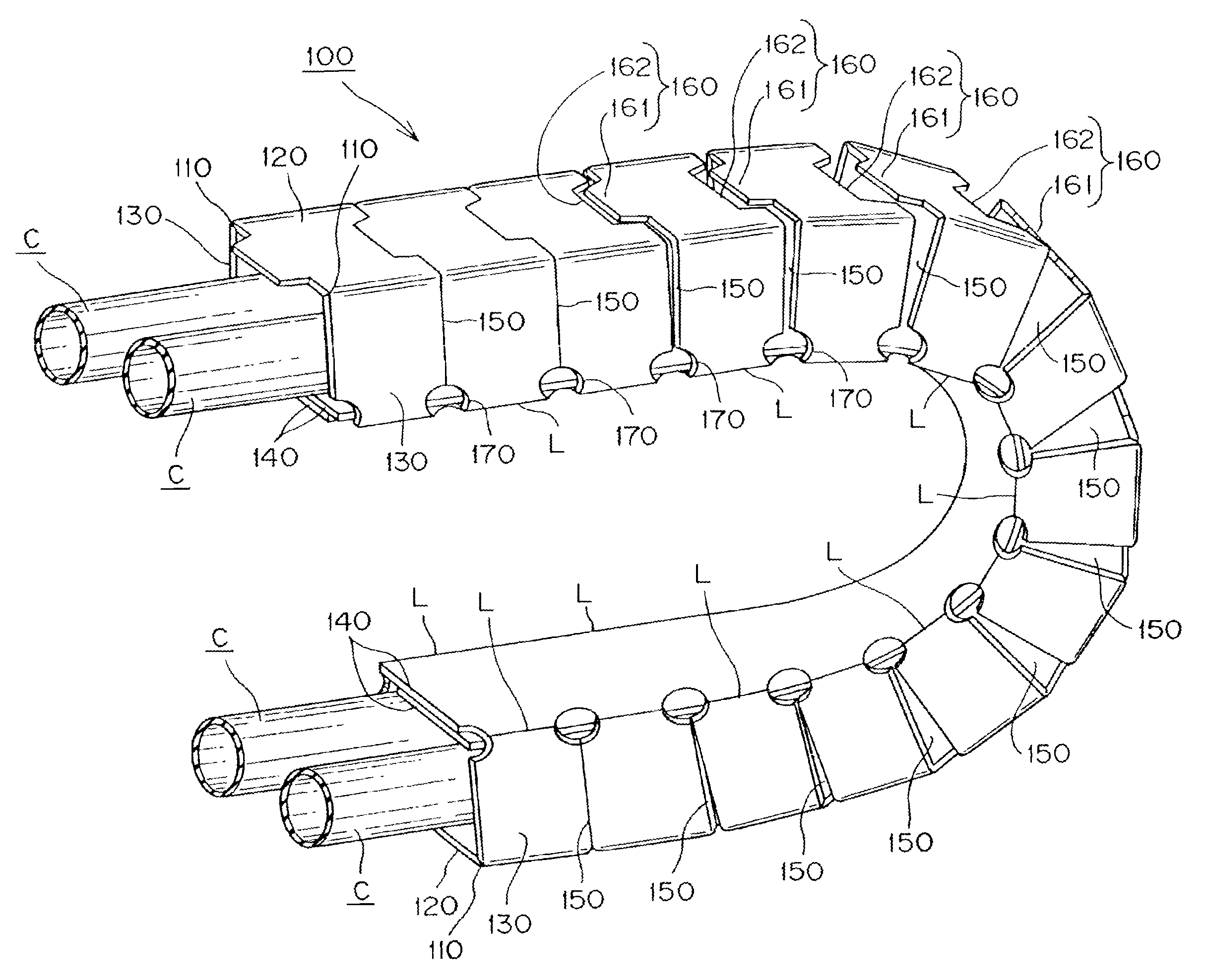
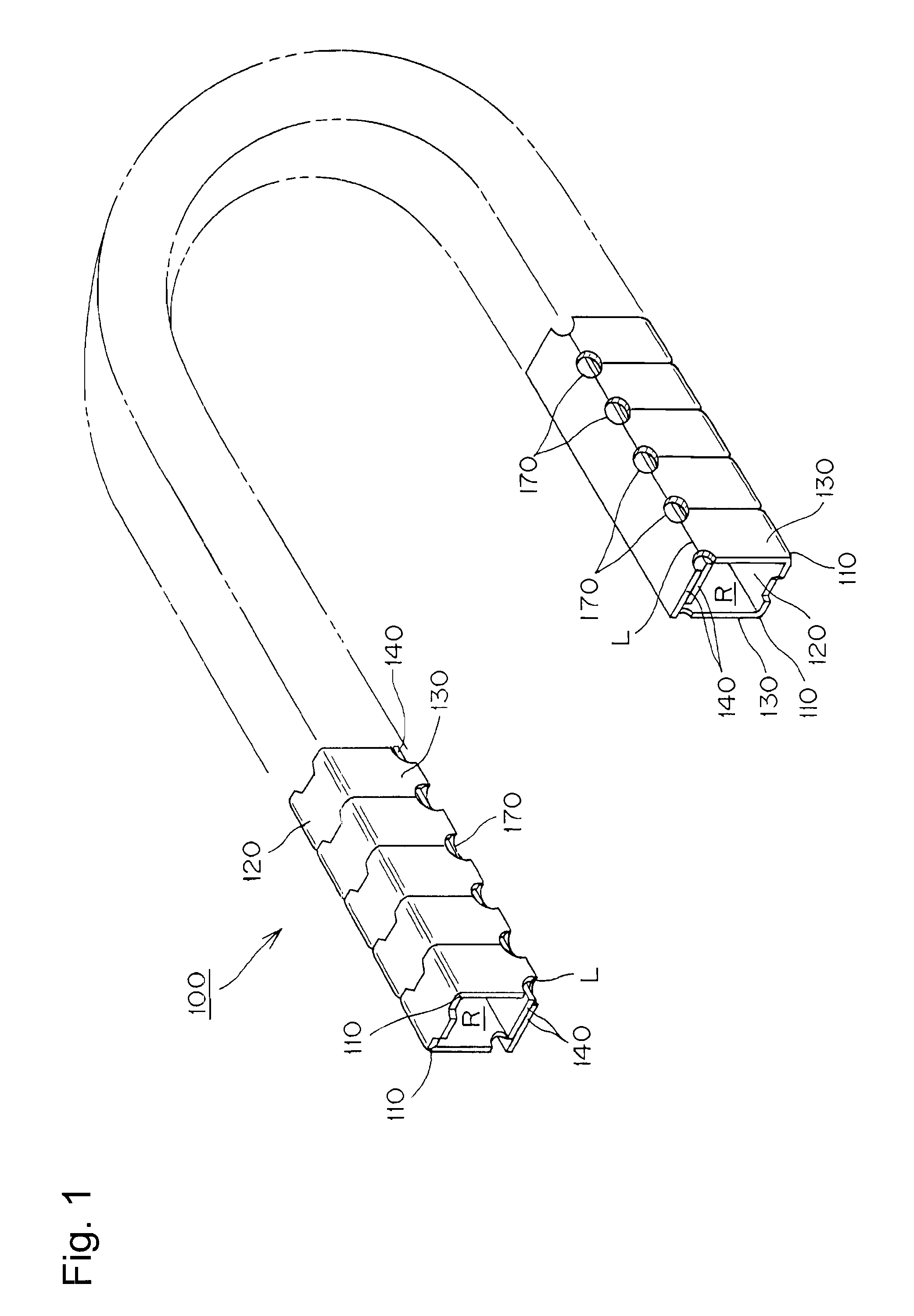
[0042]A folding type cable protection and guide device, which is an example according to the present invention, will be described with reference to FIGS. 1 and 7 below.

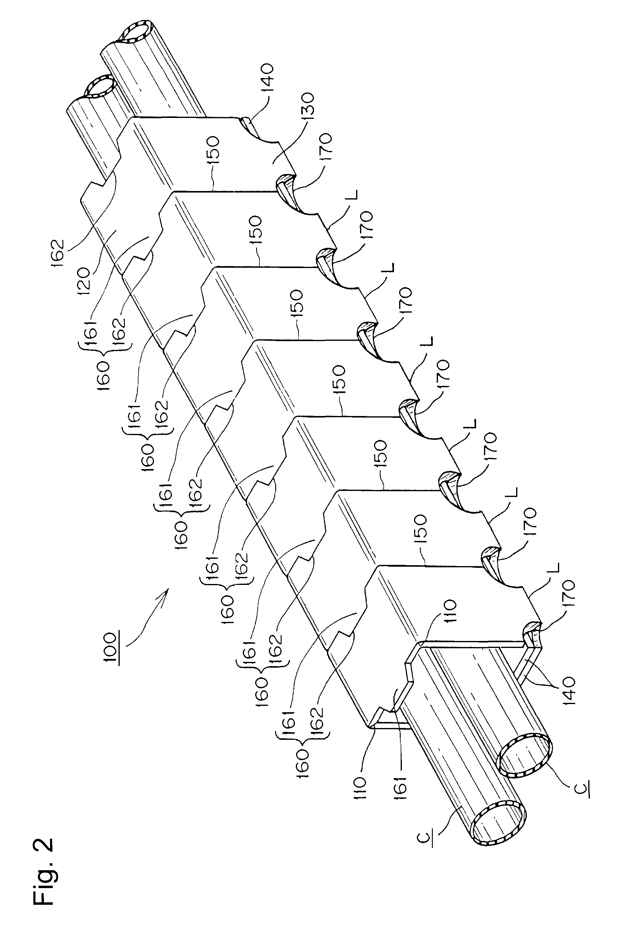
[0043]Here, FIG. 1 is an entire view showing a folding type cable protection and guide device. FIG. 2 is a perspective view of an enlarged linear state of FIG. 1. FIG. 3 is a perspective view of an enlarged flexed state of FIG. 1. FIG. 4 is a development view of a synthetic resin tape used in FIG. 1. FIG. 5 is an enlarged view showing the V section of FIG. 4. FIG. 6 is an enlarged view showing a modified example of the embodiment shown in FIG. 5. FIG. 7 is an enlarged view showing the VII section of FIG. 4.

[0044]The folding assembly type cable protection and guide device of the present example is used for connecting a movable section and a stationary section of a device and supplying the device with energy such as electric power or compressed air. Examples may include: a semiconductor device, a pharmacy developing tes...


PUM


Abstract

A folding type cable protection and guide device is provided in which a cable is accommodated into a cable accommodating space. The cable accomodating space can be easily adapted to accommodate the cable, even if the cable is a long body. The assembly load is decreased. Further, the use of many different sized metal molds is not required. The form stability of the cable accommodating space is sufficiently ensured during both linear movement and flexion movement, so that smooth linear movement and flexion movement can be attained. The rectangularly shaped cable accommodating space is formed by folding a pair of right and left folded sections 110, 110 extending in a longitudinal direction of the extruded synthetic resin tape 100 along the longitudinal direction of the tape.

Description

[0001]This application claims priority to Japanese Pat. Appln. 2006-254637 filed Sep. 20, 2006.[0002]The present invention relates to a cable protection and guide device. More specifically, it relates to a cable protection and guide device suitable for accommodating a comparatively light weight and small diameter cable which supplies a movable member with energy such as electric power or compressed air. Examples include: a semiconductor device, a pharmacy developing testing device, a vehicle door opening / closing device, a vehicle slide seat, and a vehicle motor sunroof. The cable protection and guide device safely and reliably guides and protects a cable (cables) even during movement of the portable member.BACKGROUND TECHNOLOGY[0003]Conventional cable protection and guide devices for cables / hoses are known in the prior art. In the conventional device, the upper edges and lower edges of pairs of oppositely spaced and similarly shaped link plates are respectively connected with flaps ...

Claims


Application Information

Patent Timeline
Patent Type & Authority Patents(United States)
IPC IPC(8): F16L11/00
CPCF16G13/16H02G11/00H02G3/0475F16L3/015H01B7/24H01B17/58H02G11/006
Inventor KOMIYA, SHOICHIROMATSUDA, TAKAYUKI
Owner TSUBAKIMOTO CHAIN CO
Why Eureka
Try Eureka