Drum shell formation

Active Publication Date: 2011-05-17
DRUM WORKSHOP
View PDF19 Cites 5 Cited by
  • Summary
  • Abstract
  • Description
  • Claims
  • Application Information

AI Technical Summary

Benefits of technology

[0018]Yet another object is to provide apparatus for treating plywood drum shells to enhance consistency

Problems solved by technology

During that process, the annular shape of the drum shell can and does distort leading to problems in use of the final drum.
However, through many years of experience and research it was discovered that the failure rate of realizing both of these two elements is fairly high i.e.; dry whether, cold-damp weather, heat, moisture,

Method used


Image

  • Drum shell formation
  • Drum shell formation
  • Drum shell formation

Examples


Embodiment Construction

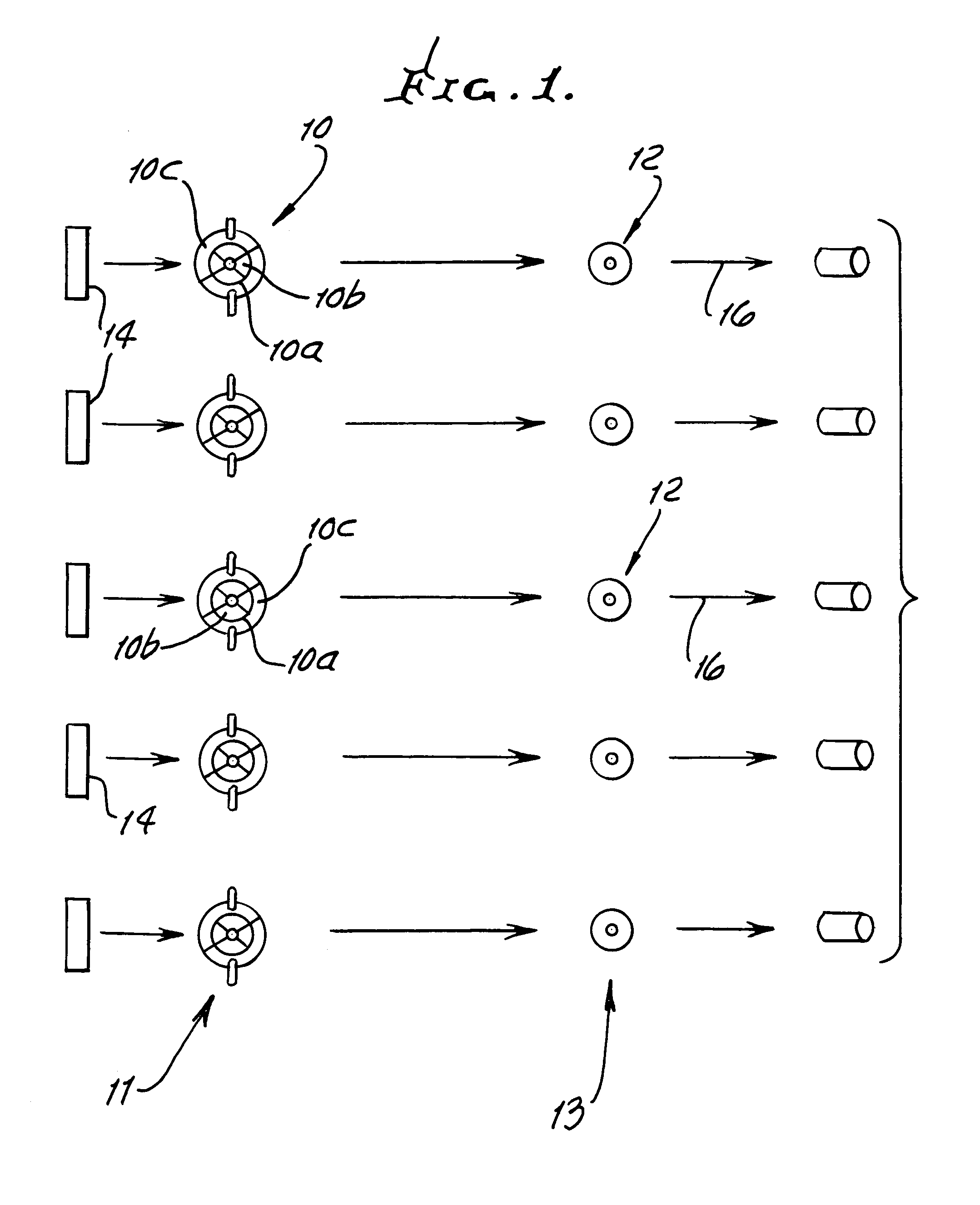
[0032]In FIG. 1, a first bank of drum shell heating platens 10 is shown at 11; and a second bank of drum shell cooling platens 12 is shown at 13. Plywood blanks 14 are received by and between inner and outer platens, as at 10a, to receive heat and pressure to adhesively bond the plies together in cylindrical configuration. Inner platen cylindrical segments appear at 10b, and outer platen cylindrical segments appear at 10c. After time T between the platens 10, the latter are adjusted to allow removal of the formed hot shells, and transfer thereof to the cooling inner and outer platens 12. Therein, heat is withdrawn from the shells, kept at high pressure exerted against inner and outer side walls of the shells, i.e. maximum heat transfer wall area with surface-to-surface contact is utilized for efficient, uniform, and rapid cooling, without distortion. Platens 12 are like platen 10, but are kept cooled.

[0033]Thereafter, the shells are removed from bank 13, as shown at 16. During such ...


PUM


Abstract

In the method of forming a drum shell that consists of plywood, the steps that includes forming the shell under pressure and heat into cylindrical configuration, providing inner and outer cooling platens adapted to respectively engage the interior and exterior surfaces of the heated shell, trapping the heated shell between the platens, at elevated pressure, allowing the shell to cool by heat transfer from shell side wall or walls into pressure exerting side walls, and while trapped between such platens, at elevated pressure, and removing the cooled shell from between the cooling platens.

Description

BACKGROUND OF THE INVENTION[0001]This invention relates generally to the formation of drum shells consisting of wood, such as plywood; and more particularly the invention concerns cooling of shells after their formation in annular configuration, under heat and pressure.[0002]Multi ply drum shells are typically made of plywood consisting of single ply, 2 ply and 3 ply cross laminate lay ups. Drum shells may consist of a combination of those factors.[0003]When such plies are rolled together with glue (or any type of adhesive) and inserted into a mold, there are two elements that work together to form the shell-pressure and heat. The mold (also known as a heating device or drum shell machine) typically has an outer platen and an inner platen, which work via hydraulics, as well as serving as heating elements. The outer platen closes to establish the outside diameter of the shell. The inner platens, provided with a tapered pin to displace them, spreads the inner platens toward the outer ...

Claims


Application Information

Patent Timeline
IPC IPC(8): B27H1/00
CPCB27D1/086B27D1/083
Inventor GOOD, JOHN J.
Owner DRUM WORKSHOP
Why Eureka
Try Eureka