Projecting device having a heat-dissipating mechanism

a projecting device and heat dissipation mechanism technology, applied in projectors, lighting and heating equipment, instruments, etc., can solve the problems of inability of axial fans to effectively overcome the high air impedance characteristic associated with thin-type projector systems, inability of axial fans to resist air impedance, etc., to achieve the effect of enhancing system reliability and improving heat dissipation

Active Publication Date: 2011-05-17
CORETRONIC
View PDF2 Cites 0 Cited by
  • Summary
  • Abstract
  • Description
  • Claims
  • Application Information

AI Technical Summary

Benefits of technology

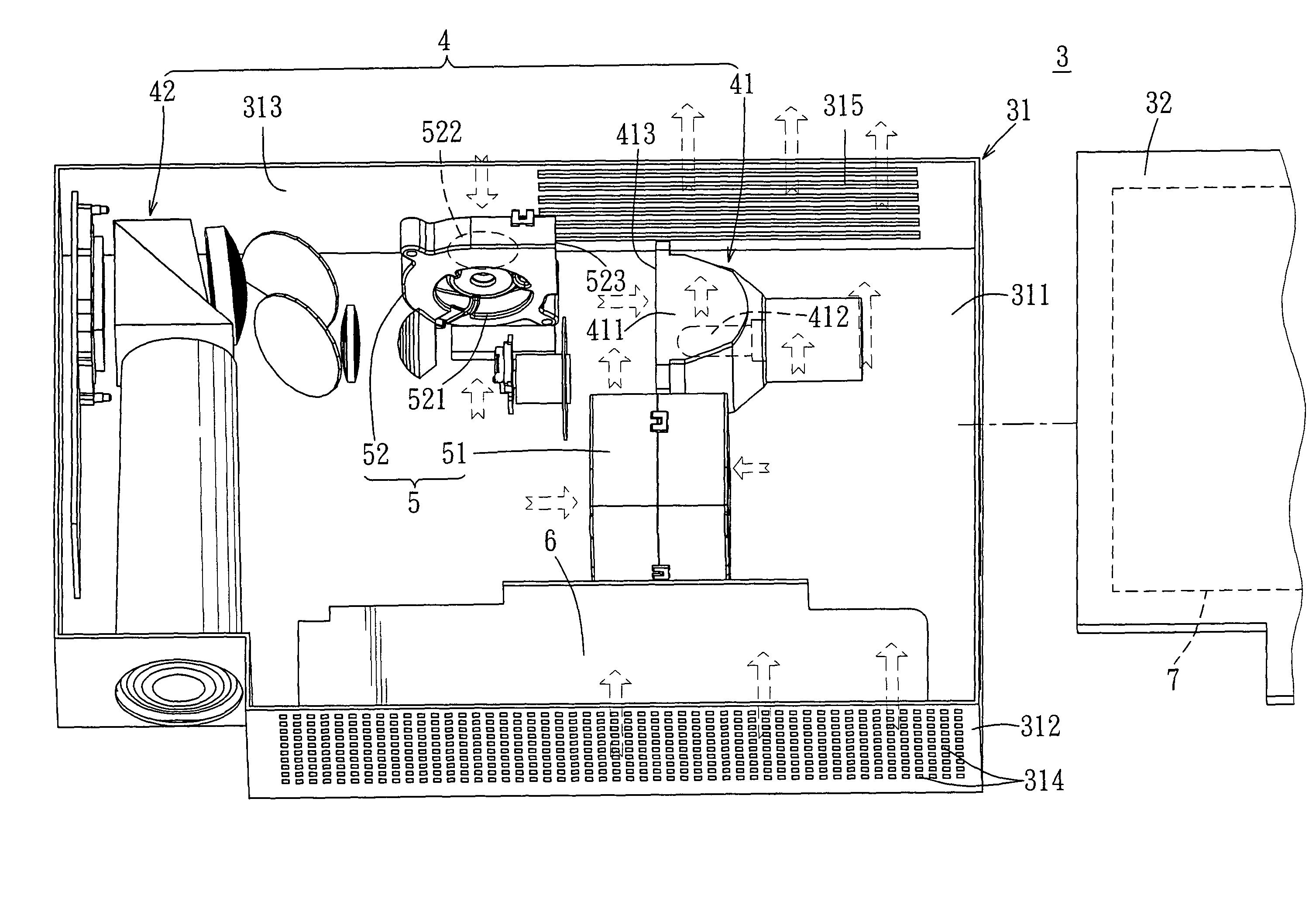
[0009]Therefore, an object of a preferred embodiment of the present invention is to provide a projecting device which, by means of arrangement of a blower of a heat-dissipating mechanism therein, is capable of providing a sufficient amount of airflow for a system to improve heat dissipation and enhance system reliability.
[0017]Due to the arrangement of at least one first blower having the characteristics of providing high static pressure and a relatively high amount of airflow, the projecting device of a preferred embodiment of this invention provides a sufficient amount of airflow for the system to improve the heat-dissipating effect and enhance the reliability of the system, while reducing noise in the interior of the system. In addition, the arrangement of the first blower enhances flexibility in use, reduces the size of the casing in design so as to facilitate carrying, and at the same time lowers manufacturing and transport costs.

Problems solved by technology

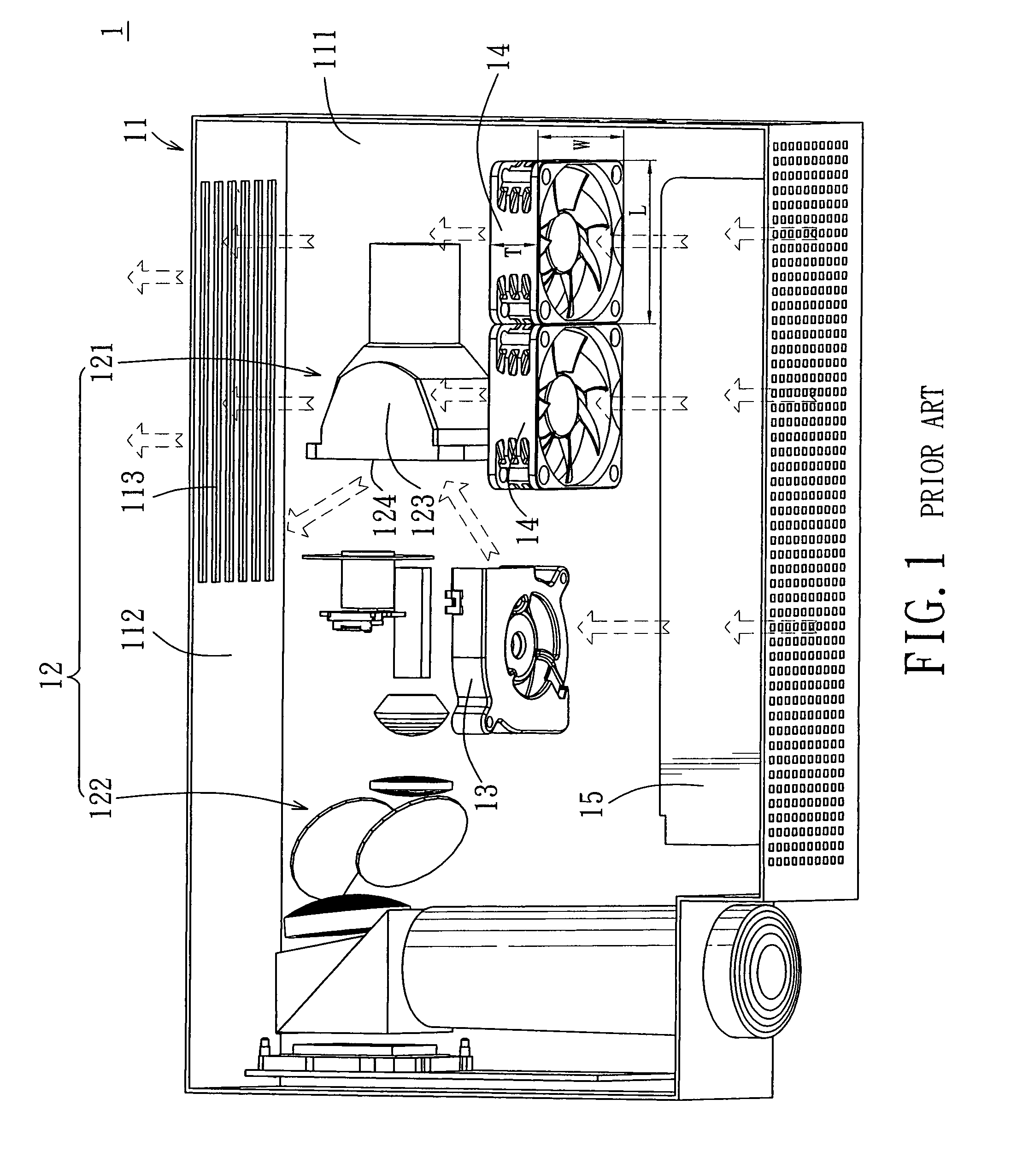
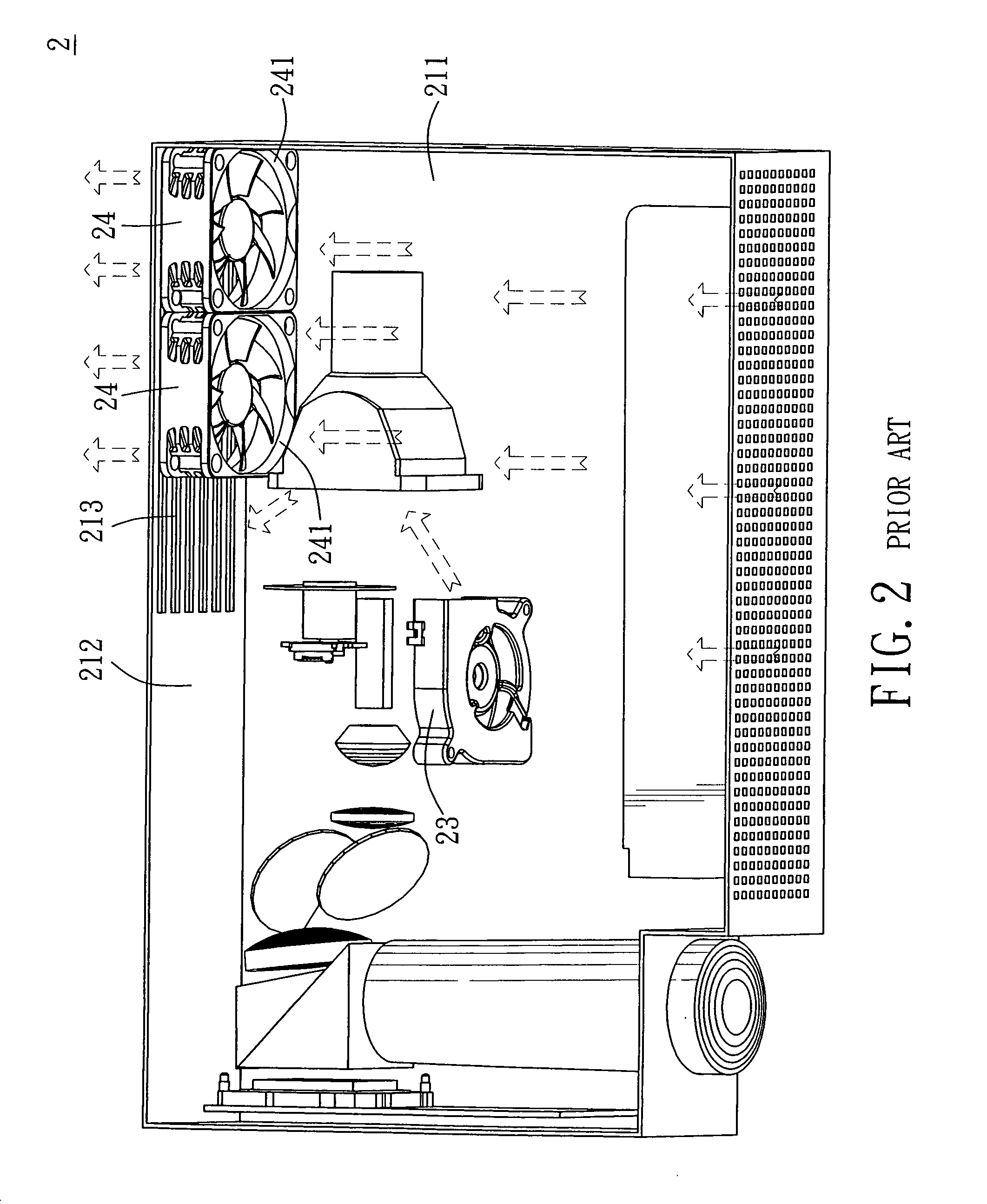
However, the maximum static pressure that the axial fan 14 can provide is 0.1 in H20. That is, the capability of the axial fan 14 to resist air impedance is limited, and the axial fan 14 is incapable of effectively overcoming the high air impedance characteristic associated with a thin-type projector system.
This apparently cannot meet the requirements of the projector 1 which requires the amount of airflow of 10 CFM, thereby resulting in increased temperature during operation of the burner of the light source module 121.
Therefore, the actual output efficiency is evidently unsatisfactory.
However, in order to effectively provide the system with a sufficient amount of airflow, except for the thickness of the blower which is required to match the thickness of the casing and is therefore unalterable, the length and width of the blower need to be sufficiently large, so that the static pressure value of the blower is increased to provide airflow required by the system.
Such an arrangement inevitably results in an increase in length and width of the casing of the projector, so that the projector occupies a relatively larger amount of space in use, and renders carrying of the projector inconvenient.

Method used


Image

  • Projecting device having a heat-dissipating mechanism
  • Projecting device having a heat-dissipating mechanism
  • Projecting device having a heat-dissipating mechanism

Examples


Embodiment Construction

[0030]In the following detailed description of the preferred embodiments, reference is made to the accompanying drawings which form a part hereof, and in which are shown by way of illustration specific embodiments in which the invention may be practiced. In this regard, directional terminology, such as “top,”“bottom,”“front,”“back,” etc., is used with reference to the orientation of the Figure(s) being described. The components of the present invention can be positioned in a number of different orientations. As such, the directional terminology is used for purposes of illustration and is in no way limiting. On the other hand, the drawings are only schematic and the sizes of components may be exaggerated for clarity. It is to be understood that other embodiments may be utilized and structural changes may be made without departing from the scope of the present invention. Also, it is to be understood that the phraseology and terminology used herein are for the purpose of description an...


PUM


Abstract

A projecting device includes a casing, an optical engine, and a heat-dissipating mechanism. The casing includes a lower casing body and an upper casing body covering the lower casing body. The optical engine is disposed in the casing, and includes a light source module. The heat-dissipating mechanism includes a first blower disposed uprightly in the casing and adjacent to one side of the light source module for driving airflow to cool the light source module and the casing. The first blower has a thickness greater than one half of a length thereof and greater than one half of a width thereof. With the arrangement of the first blower, a sufficient amount of airflow is provided to the system to improve the heat-dissipating effect and to enhance system reliability.

Description

CROSS-REFERENCE TO RELATED APPLICATION[0001]This application claims priority of Taiwanese Application No. 096120729, filed on Jun. 8, 2007.BACKGROUND OF THE INVENTION[0002]1. Field of the Invention[0003]The invention relates to a heat-dissipating mechanism for a projecting device, more particularly to a heat-dissipating mechanism for a thin-type projecting device.[0004]2. Description of the Related Art[0005]Referring to FIG. 1, a conventional projector 1 includes a casing 11, and an optical engine 12, a blower 13, two axial fans 14, a power supply 15, and a control circuit board (not shown) disposed in the casing 11. The casing 11 includes a lower casing body 111 and an upper casing body (not shown) covering the lower casing body 111. The optical engine 12 includes a light source module 121 disposed in the lower casing body 111, and an imaging module 122. The light source module 121 includes a lampshade 123 and a burner (not shown) disposed in the lampshade 123. The light source mod...

Claims


Application Information

Patent Timeline
Patent Type & Authority Patents(United States)
IPC IPC(8): G03B21/26
CPCG03B21/16
Inventor HSU, NIEN-HUIWU, SHANG-HSUANGWU, PEL-YU
Owner CORETRONIC
Why Eureka
Try Eureka