Optimizing converter protection for wind turbine generators

a technology for wind turbine generators and converter protection, which is applied in the direction of electric generator control, machines/engines, mechanical equipment, etc., can solve the problems of overheating of generators and/or transformers, overheating of individual converter circulating current, and large and costly filters

Active Publication Date: 2011-05-17
GE INFRASTRUCTURE TECH INT LLC
View PDF12 Cites 44 Cited by
  • Summary
  • Abstract
  • Description
  • Claims
  • Application Information

AI Technical Summary

Benefits of technology

[0021]The present invention relates to a structure and method for providing protection for wind turbine generator converter systems against catastrophic damage during fault conditions and also provide personnel protection during these fault conditions and during maintenance.

Problems solved by technology

In order to meet both grid side and machine side power quality requirements, such systems generally use large and costly filters to smooth out pulse width modulated waveforms.
Such systems sometimes cause overheating of the generator and / or transformers and other distortion-sensitive equipment due to high harmonic components, when the large and costly filters are minimized.
However, while the net (result of the combination of converters) distortion current is reduced, the individual converter circulating current is worsened.
However, these common mode currents, as well as normal mode circulating currents, force converter switching devices and other components to operate closer to thermal limits.
Further, these common mode currents may cause a direct error in the measurement of ground fault currents of that loop, thereby making fault detection more difficult.
However, for a subsystem, such as an individual converter thread, the common connection of the individual converter threads on the generator-side and on the load-side can result in a non-zero summation of currents due to common mode currents flowing between threads.
Yet, protection of individual three phase converter threads requires rapid fault detection, isolation and repair.

Method used


Image

  • Optimizing converter protection for wind turbine generators
  • Optimizing converter protection for wind turbine generators
  • Optimizing converter protection for wind turbine generators

Examples


Embodiment Construction

[0041]The following embodiments of the present invention have many advantages, including protecting against catastrophic damage during fault conditions not previously protected for under prior art systems and fault protection analysis and also providing personnel protection during maintenance

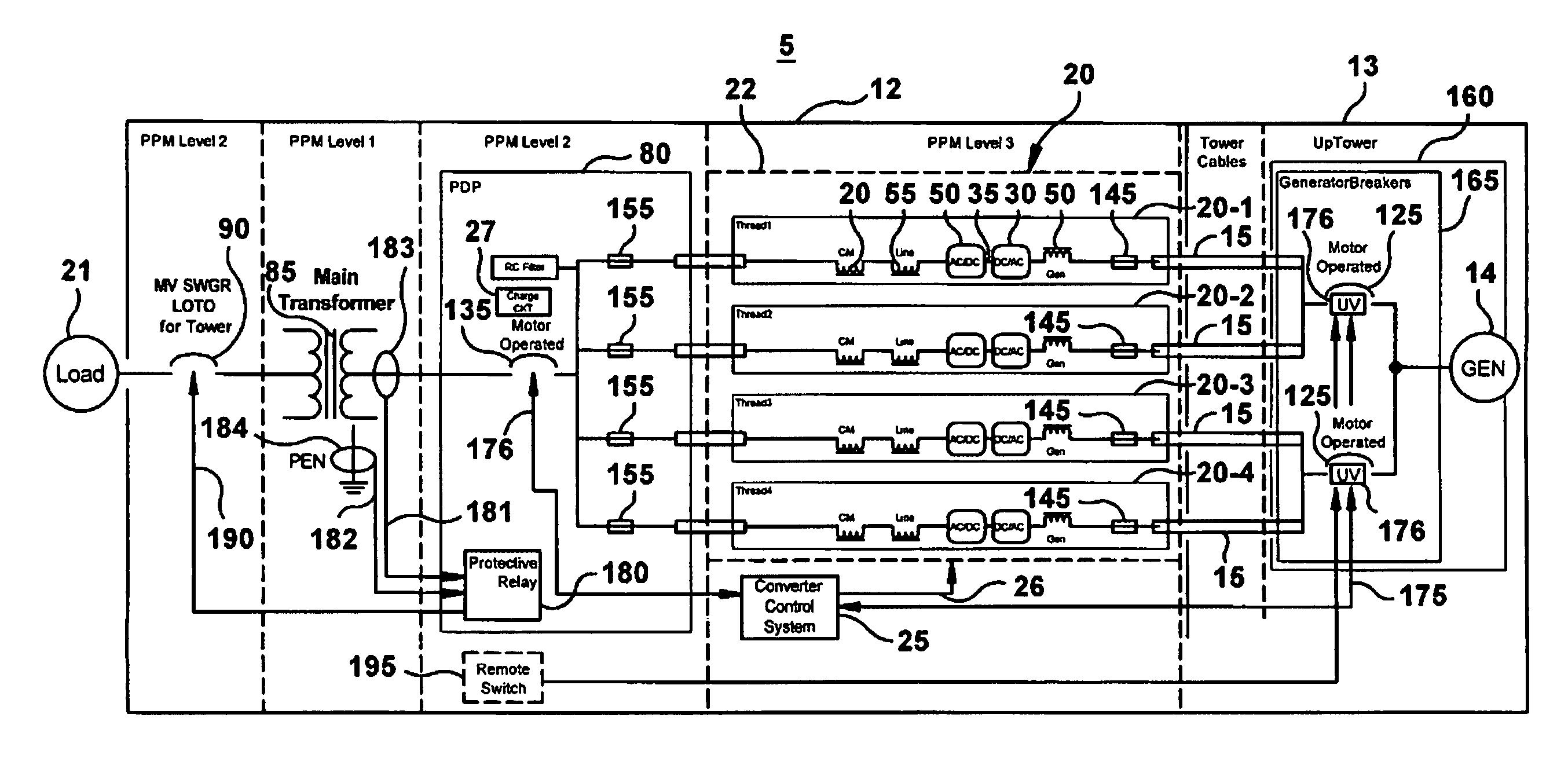
[0042]In wind turbine power conversion systems, there are two major sources of energy that must be considered in a fault scenario: the utility power grid and the wind turbine generator. Protection of the converter from these sources of energy is then a crucial task. Converter protection must also be coordinated in such a way to protect personnel in the event of an arch flash inside the converter during fault conditions. Arc flash events have been experienced in various parallel converters for wind turbine generators in the field.

[0043]The present invention provides an improvement in the data processing incorporating an advanced analysis of a multi-thread converter system operation when exposed t...


PUM


Abstract

An integrated fault and personnel protection system and method for a multi-thread converter in a wind turbine power system is provided. The structure and method provide for system optimization, as well as, arc flash protection. Fault sensing with means of removing power applied to the converter minimizes the energy available to produce an arc flash event. Sensing and disconnects devices for the protections are provided close to the source of energy to protect more of the system. Converter controls detect, identify and isolate faults selecting the best combinations of the novel specific fault isolation devices. Components are distributed into separate physical to enhance protection.

Description

BACKGROUND OF THE INVENTION[0001]The invention relates generally to wind turbine generators and more specifically to a system and method for integrated fault and personnel protection system for wind turbine power systems providing output to a load.[0002]Generally, wind turbines use the wind to generate electricity. The wind turns multiple blades connected to a rotor. The spin of the blades caused by the wind spins a shaft of the rotor, which connects to a generator that generates electricity. Specifically, the rotor is mounted within a housing or nacelle, which is positioned on top of a truss or tubular tower, which may be as high as about 100 meters. Utility grade wind turbines (e.g., wind turbines designed to provide electrical power to a utility grid) can have large rotors (e.g., 30 or more meters in diameter). Blades on these rotors transform wind energy into a rotational torque or force that drives one or more generators, rotationally coupled to the rotor through a gearbox. The...

Claims


Application Information

Patent Timeline
Patent Type & Authority Patents(United States)
IPC IPC(8): F03D9/00H02P9/00
CPCH02J3/38H02P9/006H02H7/1216H02P2101/30Y02E10/763H02P2101/15F03D80/00Y02E10/76
Inventor WAGONER, ROBERT G.RITTER, ALLEN M.KLODOWSKI, ANTHONY M.FRAME, SCOTT C.SUTHERLAND, STEVEN W.BARKER, SIDNEY A.BARTON, WERNER
Owner GE INFRASTRUCTURE TECH INT LLC
Why Eureka
Try Eureka