Apparatus and method of receiving data from audio/video equipment

a technology of audio/video equipment and data transmission apparatus, applied in the field of apparatus and methods for receiving video data via digital, can solve the problems of data transmission apparatus not being able to perform correct cec control, data transmission apparatus not being able to read the physical address of the data receiver apparatus,

Active Publication Date: 2011-05-17
HISENSE VISUAL TECH CO LTD
View PDF12 Cites 148 Cited by
  • Summary
  • Abstract
  • Description
  • Claims
  • Application Information

AI Technical Summary

Benefits of technology

[0011]The source apparatus transmits and receives data required to achieve the authentication of high-bandwidth digital content protection (HDCP), to and from the sink apparatus through the DDC line. The data required to achieve the authentication is, for example, HDCP key data. In this instance, the HDCP key data is assumed to be stored in a storage area the sink apparatus has. For the source apparatus, to authenticate the high-bandwidth digital content protection is to confirm that the sink apparatus is authorized to receive video signals. Upon authenticating the high-bandwidth digital content protection, the source apparatus decrypts the video data with the secret-key data shared with the sink apparatus, and then transmits the video data, thus decrypted, to the sink apparatus.

Problems solved by technology

Hence, the source apparatus or repeater apparatus may fail to read its own physical address, depending on whether or not power is supplied to the source, sink and repeater apparatuses and whether or not the switching device has set a signal path for any apparatus designated.
Consequently, the source apparatus #1 keeps holding the physical address of the port #1, and cannot acquire the correct physical address “2.0.0.0.” Therefore, correct CEC control may not be performed.
However, the data transmission apparatus may fail to read the physical address of the data receiver apparatus, depending on what state the apparatuses assume and which apparatus the switching device selects.

Method used


Image

  • Apparatus and method of receiving data from audio/video equipment
  • Apparatus and method of receiving data from audio/video equipment
  • Apparatus and method of receiving data from audio/video equipment

Examples


Embodiment Construction

[0024]Various embodiments according to the invention will be described hereinafter with reference to the accompanying drawings.

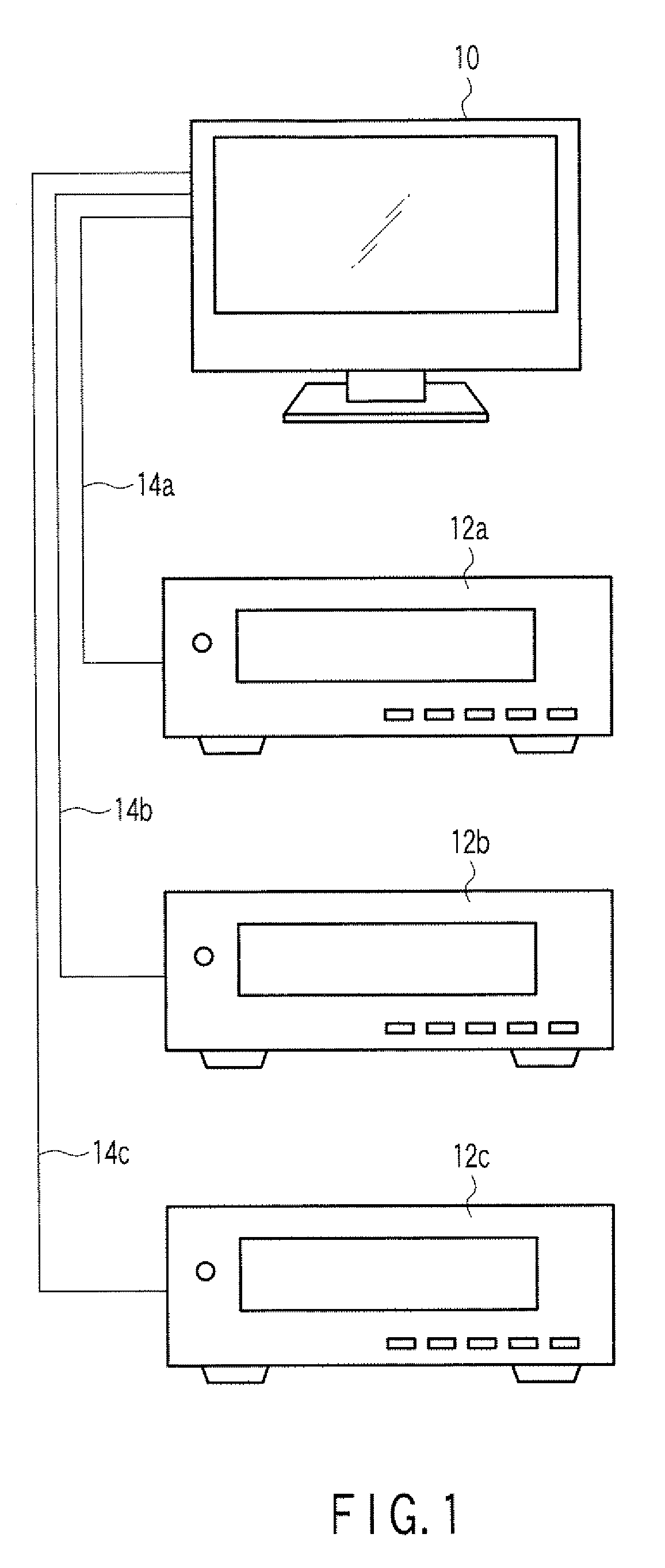
[0025]According to an embodiment, FIG. 1 is a schematic diagram showing a video system according to an embodiment of the present invention.

[0026]The video system has a video-data receiver apparatus (i.e., sink apparatus) 10 and video-data transmission apparatuses (for example, three apparatuses) (i.e., source apparatuses) 12a, 12b and 12c. HDMI cables 14a, 14b and 14c connect the video-data transmission apparatuses 12a, 12b and 12c, respectively, to the video-data receiver apparatus 10. The video-data transmission apparatuses 12a, 12b and 12c are, for example, digital versatile disc (DVD) players, streaming video-data transmission apparatuses, tuners, set-top boxes, or game apparatuses. The video-data receiver apparatus 10 is, for example, a television receiver, or a monitor for a personal computer (PC), or the like.

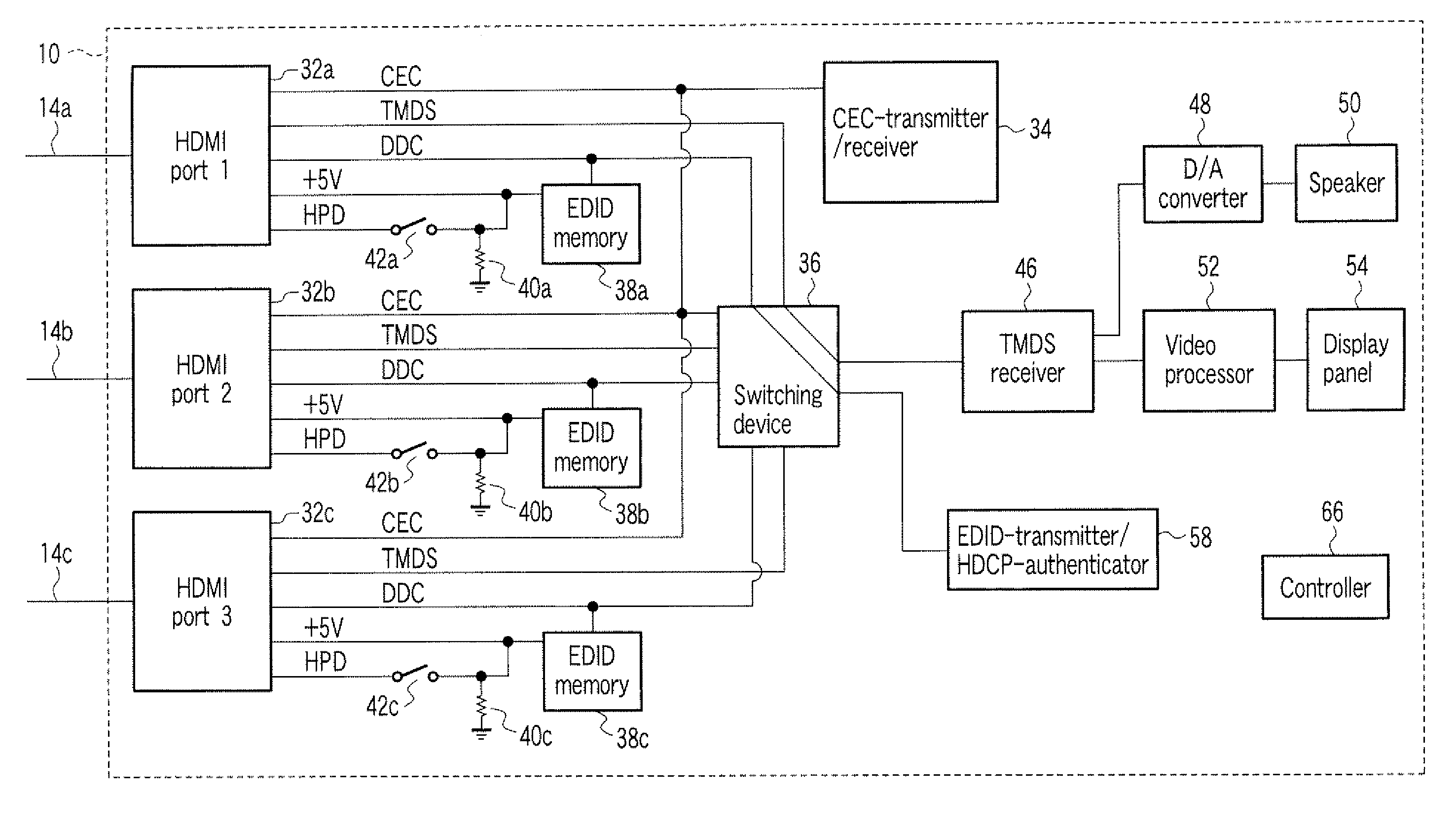
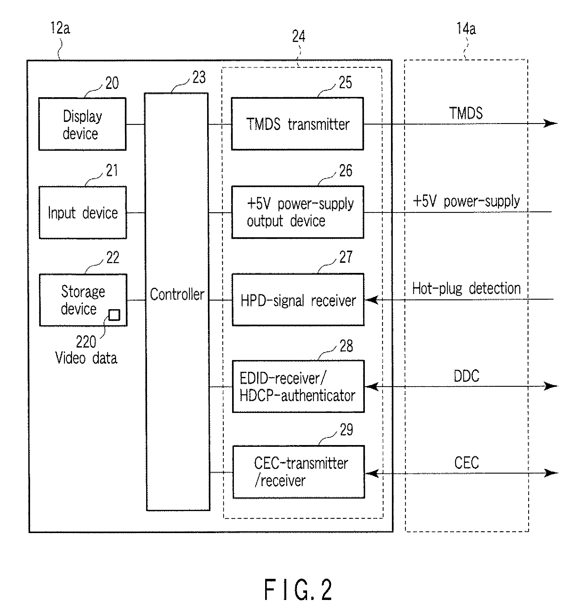
[0027]FIG. 2 is a diagram showing a config...


PUM


Abstract

According to one embodiment, a data receiver apparatus comprises input ports complying with a digital interface standard, wherein each input port comprises a voltage signal terminal receiving a prescribed voltage signal, a detection terminal outputting a connection detection signal, a data input terminal receiving a data signal, and an address terminal transmitting a physical address. A nonvolatile memory is connected to the address terminal. A connection detection signal output from the detection terminal is set to a detection-state voltage irrespective of whether the data input terminal is selected.

Description

CROSS-REFERENCE TO RELATED APPLICATIONS[0001]This is a Continuation Application of PCT Application No. PCT / JP2008 / 061599, filed Jun. 19, 2008, which was published under PCT Article 21(2) in English.[0002]This application is based upon and claims the benefit of priority from Japanese Patent Application No. 2007-166635, filed Jun. 25, 2007, the entire contents of which are incorporated herein by reference.BACKGROUND[0003]1. Field[0004]One embodiment of the invention relates to an apparatus and method for receiving video data via a digital interface.[0005]2. Description of the Related Art[0006]An example of a multimedia interface between a video-data transmission apparatus, such as a DVD player, a digital tuner and a set-top box, and a video data-data receiver apparatus, such as a TV receiver and a monitor, is one complying with the high definition multimedia interface (HDMI) standard (High-Definition Multimedia Interface Specification Version 1.3a). Any apparatus that has an HDMI outp...

Claims


Application Information

Patent Timeline
Patent Type & Authority Patents(United States)
IPC IPC(8): G06F3/00G06F13/12G06F7/04G06F13/14H04N7/173H04N21/4363H04N21/442
CPCG09G5/006H04N5/775G09G2370/047G09G2370/06H04N5/85G09G2370/12
Inventor OHKITA, HIDEKI
Owner HISENSE VISUAL TECH CO LTD
Why Eureka
Try Eureka