Patient assistance device

a technology for caregivers and wheelchairs, applied in the direction of pedestrian/occupant safety arrangements, vehicular safety arrangements, safety belts, etc., can solve the problems of lack of caregiver training, difficulty in assisting caregivers, and large volume of mechanical lifts, etc., to enhance the structural rigidity of the rear panel section, enhance the structural integrity of the unitary garment member, and enhance the structural rigidity

Inactive Publication Date: 2011-05-24
CLIFFORD PHILLIP
View PDF15 Cites 26 Cited by
  • Summary
  • Abstract
  • Description
  • Claims
  • Application Information

AI Technical Summary

Benefits of technology

[0013]The present invention overcomes many of the disadvantages of prior art lifting assistance devices by providing an improved patient assistance device that is easy to put on and take off, very comfortable to wear and highly adjustable in a matter of seconds. The improved patient assistance device includes a plurality of strategically positioned hand holds, which provide enhanced leverage enabling a caregiver to more easily assist a patient wearing the device to move from one position to another.
[0014]The patient assistance device of the present invention comprises a poncho-style garment in the form of a unitary member having a front panel section, a rear panel section and a central or middle panel section interconnecting the front and rear panel sections. The unitary garment member is generally constructed of a flexible, durable material. In one embodiment, the material comprising the unitary garment member is bonded with an anti-microbial agent for added hygienic protection. In a preferred embodiment, the unitary garment member is constructed of a composite material comprised of a polyester-blend outer shell bonded to a multi-layer sheet of neoprene rubber. Neoprene was chosen from a comfort perspective to act as padding to the patient's body to protect against potential bruising, skin tears, as well as broken bones, especially to the rib area for the frail elderly with osteoporosis. While in the preferred embodiment the front, central and rear panel sections of the unitary member are constructed from a single, homogenous piece of material, in other embodiments each panel section may be constructed separately of materials having different characteristics (e.g., buoyancy, strength, flexibility, etc.), then subsequently attached to the other panel sections.
[0015]The front panel section is sized and shaped to fit across the patient's chest area while the rear panel section is sized and shaped to fit across the patient's back. The central panel section includes an opening sized and shaped for receiving a human head therethrough. The rear panel section includes two flap portions extending laterally on opposing sides of the rear panel section. The inner-facing surface of the two flaps are covered with a layer of attachment fabric in the form of hook-and-loop type fastening members. A complementary layer of the attachment fabric covers a substantial portion of the outer-facing surface of the front panel section so that when the patient assistance device is properly configured on a patient, the two flap portions of the rear panel section can be pulled forward underneath the patient's arms and selectively attached to the outer-facing surface of the front panel section. Thus, when the two flap portions of the rear panel section are properly attached to the outer-facing surface of the front panel section, the patient assistance device effectively becomes a vest-type garment which completely surrounds the patient's torso.
[0016]The patient assistance device further includes a plurality of integral, reinforced support straps that are firmly attached to the unitary garment member. The plurality of support straps enhance the structural integrity of the unitary garment member by transferring and distributing a load applied to one support strap to the entire patient assistance device. The plurality of support straps include two laterally spaced shoulder support straps that are positioned over the patient's shoulders and extend the length of the unitary garment member. In addition, two back support straps are configured in a criss-cross or crossbuck arrangement across the rear panel section. The ends of the back support straps are attached to the two shoulder support straps, thereby enhancing the structural rigidity of the rear panel section. Similarly, the front panel section includes a lateral support strap that extends between the two shoulder support straps enhancing the structural rigidity of the front panel section. Finally, each flap portion of the rear panel section includes a support strap that is laterally spaced from its respective shoulder support strap.
[0017]The patient assistance device further includes more than one strategically positioned hand holds that are attached to the support straps. The hand holds provide enhanced leverage, which enables a caregiver to more easily assist a patient wearing the device to move from one position to another, while keeping the upper torso of the patient stabilized during the transfer process. In one embodiment, the hand holds comprise straps of reinforced webbing material attached to the support straps. In a preferred embodiment, the hand holds further comprise plastic handles attached to the straps.
[0018]The patient assistance device may further include one or more grommets, which improve the breathability of the garment member, further enhancing the comfort of the patient wearing the assistance device. In one embodiment, the rear panel section may include a plurality of grommet holes to provide additional breathability.

Problems solved by technology

In particular, persons confined to wheelchairs, are often unable to stand on their own and require the assistance of one or more caregivers to move them from a wheelchair or other seating arrangement or to a standing position, or oftentimes to get into and out of a bath or shower chair.
For example, a variety of mechanical lifts, which include both manual, hydraulic and electrical devices, are known to be very bulky and hard to maneuver in small areas such as the bathroom, especially once the patient has been lifted and is in the sling.
In the healthcare setting, like a nursing home or hospital, some of the most common drawbacks are 1) lack of training to caregivers / nurses to properly utilize the equipment, and 2) caregivers / nurses typically take several minutes to transfer a patient.
Similarly, the prior art waist or “gait” belt devices have also proven problematic.
Some of the commonly known drawbacks of gait belt devices include 1) they are uncomfortable for the patient, 2) they have a tendency to slide up or down during transfer, 3) they can contribute to a patient falling due to the fact that the upper torso of the patient is never stabilized during the transfer process, and 4) they can cause skin tears, bruising, as well as inappropriate touching to the patient.
In addition, when a gait belt device is used to transfer a patient, the caregiver puts themselves at risk to potential injury (e.g., back and shoulder injuries), especially if this transfer position is repeated over and over.
While prior art sit-to-stand lifting / transfer devices are quicker than the traditional mechanical lift, they also exhibit several common drawbacks, including 1) they typically require the patient to be able to hold onto handles while the patient is lifted up, 2) they are also bulky and hard to push once the patient is in the device, and 3) they are also very difficult to get in and out of toilet and bathing areas.
Such manual grasping techniques are usually difficult and oftentimes dangerous to both the patient and the caregiver.
In other instances, to gain leverage caregivers grab articles of clothing such as a trouser seat or shirt collar, however, these garments are not designed or adapted for easy grasping, and sometimes tear, and require a strong grip on the part of the caregiver.
This technique is not only uncomfortable for the patient, it can also cause bruising, skin tears, or even contribute to a patient falling and sustaining more serious injuries.
Further, because of the difficulty of grasping hold of a patient that needs to be moved from one position to another, a caregiver frequently sustains injuries to himself or herself such as an injured back.
Injuries to caregivers are particularly likely due to the arching of the back in an unfavorable ergonomic position when attempting to assist a patient with transfer.
However, the garment vest is not part of the skeletal lifting structure of the device.
Moreover, the configuration of the Cohen garment vest itself can be difficult for patients in a supine position or with limited arm and shoulder flexibility to put on or to remove.
Moreover, the Cohen vest can also cause irritability underneath the armpits as the vest has a tendency to slip upwards during transfer.
In addition, when the caregiver grabs the lifting straps to attempt a transfer, a lot of pressure is applied to the harness areas due to the fact the garment material is made of a light weight fabric, which does not provide padding for comfort, and can cause bruising, even broken ribs, especially when transferring the elderly person with osteoporosis.
Lastly, the Cohen vest cannot be used by multiple patients in a healthcare setting without risking the spread of infectious diseases from one patient to another.
While useful in some situations, the handholds of the Farnum design do not provide adequate leverage to a caregiver in all situations.
For example, the Farnum design does not include any means for grasping a patient's chest or shoulder area.
In addition, it is oftentimes useful for a patient to keep a lifting garment on for an extended period of time or a wide variety of activities.

Method used


Image

  • Patient assistance device
  • Patient assistance device
  • Patient assistance device

Examples


Embodiment Construction

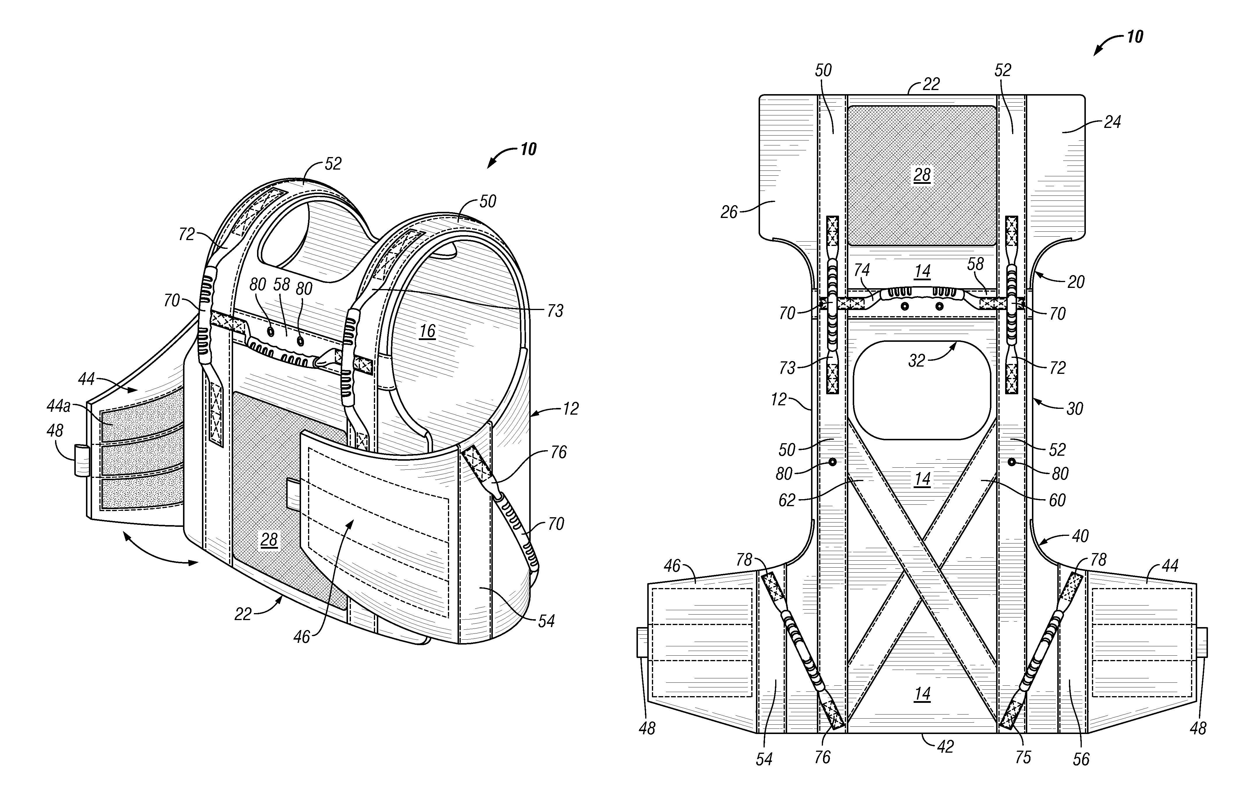
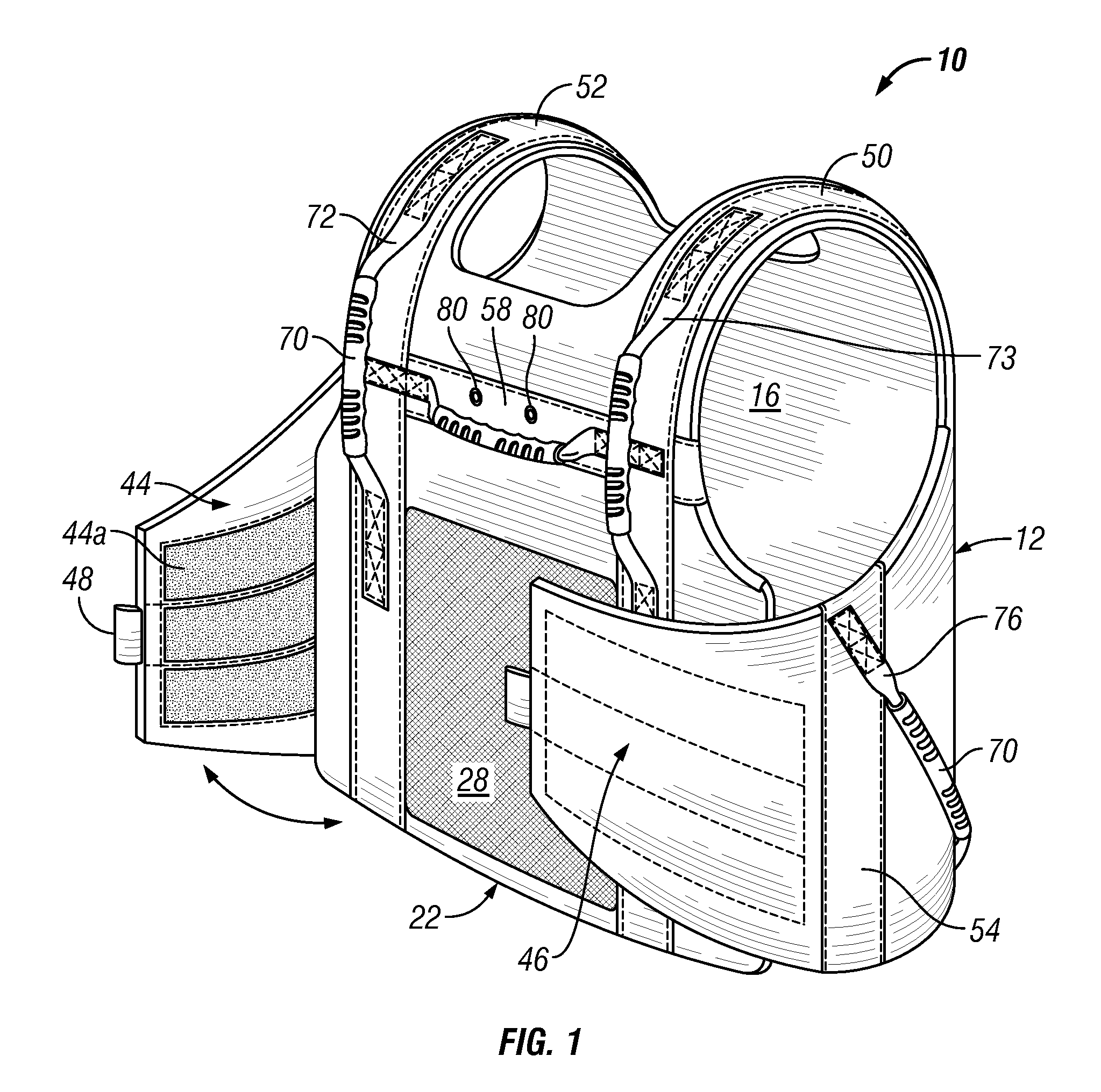
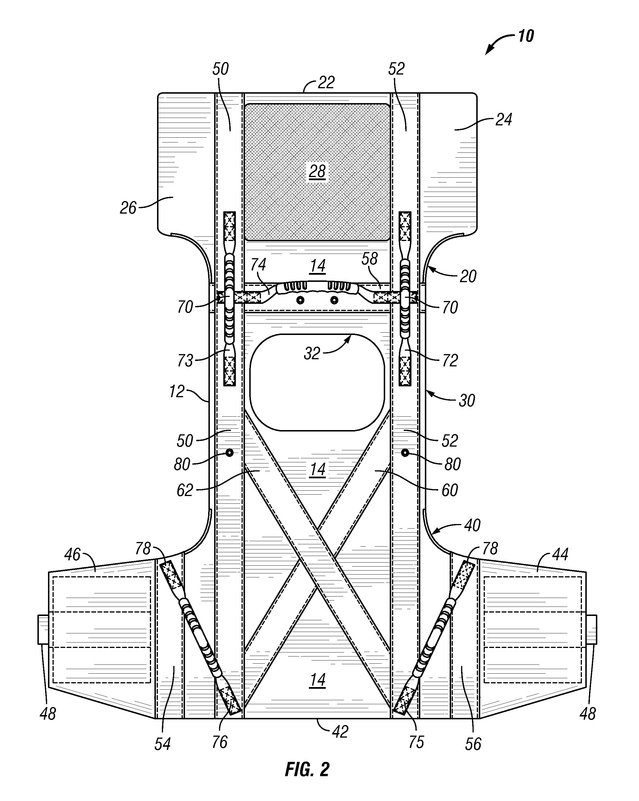
[0028]With reference to the Figures, and in particular FIGS. 1 and 2, an embodiment of the patient assistance device 10 of the present invention is shown. The patient assistance device 10 comprises a reinforced poncho-vest garment worn by a patient. The device 10 assists caregivers in lifting and moving the patient in a wide variety of scenarios. The device 10 is designed to be easily donned and removed from a patient.

[0029]The patient assistance device 10 of the present invention comprises a poncho-style garment in the form of a unitary member 12 having a front panel section 20, a rear panel section 40 and a central or middle panel section 30 interconnecting the front and rear panel sections. The front panel section 20 is sized and shaped to fit across the patient's chest area while the rear panel section 40 is sized and shaped to fit across the patient's back. The central panel section 30 includes an opening 32 sized and shaped for receiving a patient's head therethrough. The fron...


PUM


Abstract

An improved device for assisting a caregiver in lifting and moving a patient. The device comprises a unitary garment member having a front panel section, a rear panel section and an interconnecting central or middle panel section. The device further includes a plurality of integral, reinforced support straps that enhance the structural integrity of the garment member. The rear panel section includes two flap portions extending laterally on opposing sides of the rear panel section. The two flap portions can be pulled forward and attached to the front panel section whereby the device becomes a vest-type garment that completely surrounds the patient's torso. The improved patient assistance device includes a plurality of strategically positioned hand holds, which provide enhanced leverage enabling a caregiver to more easily assist a patient wearing the device to move from one position to another.

Description

BACKGROUND OF THE INVENTION[0001]1. Technical Field of the Invention[0002]The present invention relates to an apparatus for assisting a caregiver in the lifting and / or positioning of a disabled person or patient. In particular, the present invention relates to an apparatus for assisting both the caregiver, as well as a person / patient who can partially bear weight, yet needs assistance with transferring and / or repositioning.[0003]2. Description of the Related Art[0004]A variety of proposals have previously been made to provide some type of patient lifting or transfer devices that enables a caregiver to safely assist a patient in moving from one position to another. By “patient” is meant any person irrespective of age, sex, health condition, physical impairment or disability that requires, even if only occasionally, assistance in moving or transferring. Such incapacitated individuals, whether short-term or long-term, oftentimes require assistance from another person when being moved, ...

Claims


Application Information

Patent Timeline
Patent Type & Authority Patents(United States)
IPC IPC(8): A61G1/00A41D1/04
CPCA61G7/1023
Inventor THOMAS, JOHN A.CLIFFORD, PHILLIP A.
Owner CLIFFORD PHILLIP
Why Eureka
Try Eureka