Ultrasound color flow imaging at high frame rates

Active Publication Date: 2011-05-24
SIEMENS MEDICAL SOLUTIONS USA INC
View PDF14 Cites 7 Cited by
  • Summary
  • Abstract
  • Description
  • Claims
  • Application Information

AI Technical Summary

Benefits of technology

[0003]By way of introduction, the preferred embodiments described below provide a method and system for ultrasound color flow imaging at high frame rates. In one preferred embodiment, a plurality of transmit ultrasound beams are generated, with each beam comprising a different center frequency and being directed at a different spatial location. A plurality of receive ultrasound beams responsive to the plurality of transmit ultrasound beams are recei

Problems solved by technology

However, these methods and systems are only direct

Method used


Image

  • Ultrasound color flow imaging at high frame rates
  • Ultrasound color flow imaging at high frame rates
  • Ultrasound color flow imaging at high frame rates

Examples


case 1

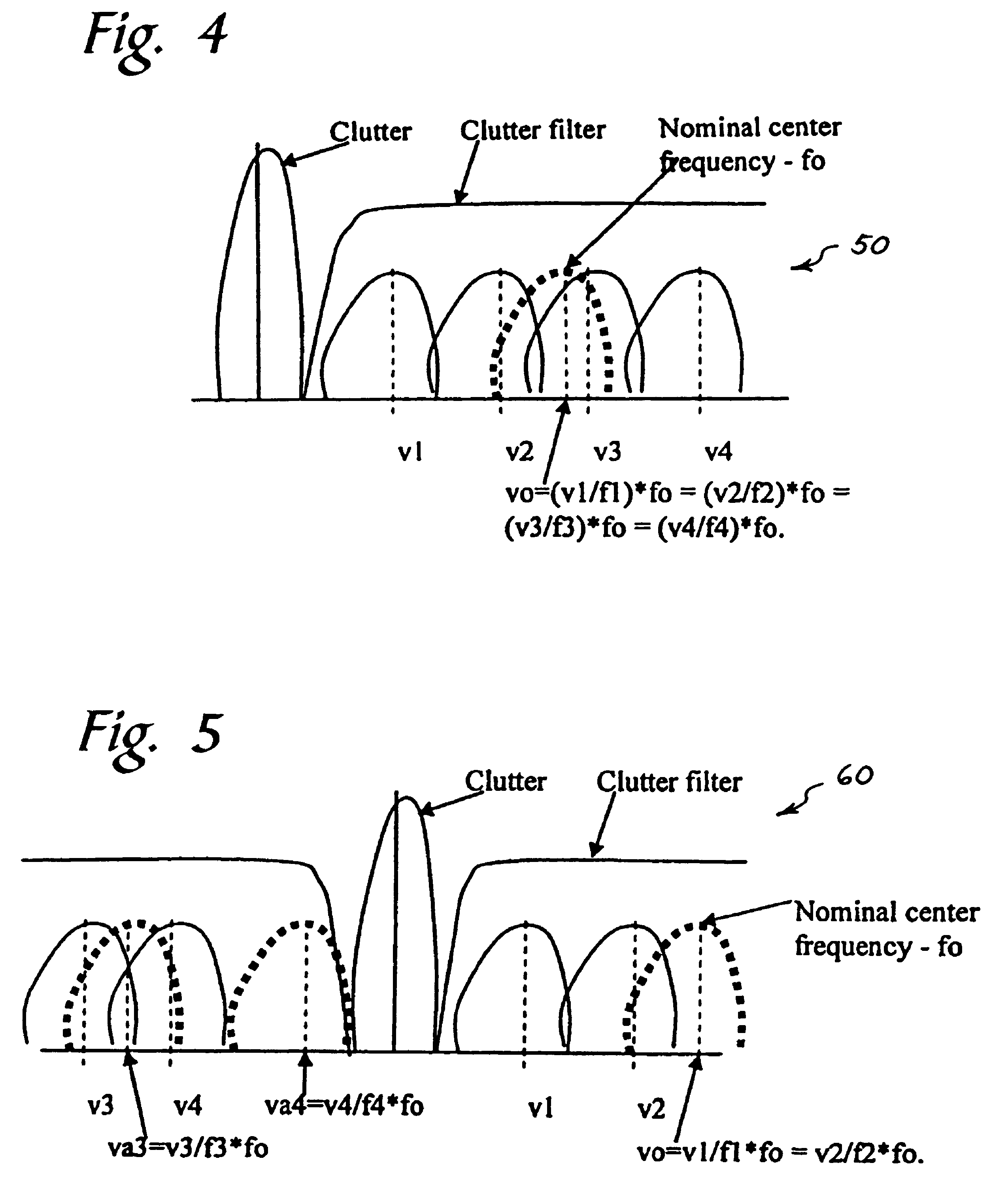
[0059] all estimates are aliased; Let the estimated velocities before correction be v1=0.2, v2=0.3, v3=0.4, v4=0.6. For the nominal frequency fo=1.75, all estimates produce a velocity vo of 0.35;

case 2

[0060] estimates at f1 and f2 are zero due to low Doppler frequencies suppressed by the stopband of the clutter filtering; Let the estimated velocities before correction be v1=0.0, v2=0.0, v3=0.2, v4=0.3. During correction, step 3 above results in nonzero estimates for f1 and f2 as v1=0.1 and v2=0.15. For the nominal frequency fo=1.75, all estimates produce a velocity vo of 0.175;

case 3

[0061] estimates at f3 and f4 are aliased; Let the estimated velocities before correction be v1=0.5, v2=0.75, v3=1.0, v4=0.5 and vmax=1.0. During correction, step 5 above results in unaliased estimates for f3 and f4 as v3=1.0 and v4=1.5. For a nominal frequency fo=1.75, all estimates produce a velocity vo of 0.875;


PUM


Abstract

A method is provided to improve the frame-rate in color-flow ultrasound imaging using simultaneous spatially-distinct transmit beams with one or more frequency bands per transmit beam. Pulses of different center frequencies are used simultaneously in different (lateral and/or elevational) directions, thereby reducing the scanning time and improving the frame-rates. Optionally, a multi-modal pulse is used, and flow is estimated separately for the different frequencies. The flow estimates for these pulses are appropriately combined to improve low-velocity sensitivity and to reduce aliasing. A flow sample count with two or more different pulse repetition intervals can be used to further improve low-flow sensitivity and minimize aliasing.

Description

BACKGROUND[0001]Color Doppler flow imaging is used in medical diagnostic ultrasound imaging systems to measure the flow velocity of fluid or tissue under examination. Because of the larger number of ultrasound pulses that need to be transmitted and received to estimate and display flow velocity, the frame rate is much lower than that of B-mode imaging. Accordingly, to display flow velocity in real-time along with a B-mode image, flow velocity is displayed in a “color box” that is smaller than the whole field of view of the B-mode image. There is, therefore, a need to improve the frame rate of color flow imaging. U.S. Pat. No. 6,159,153 describes systems and methods for improving frame rates in B-mode imaging by using multiple firing directions and multiple frequencies. However, these methods and systems are only directed to B-mode imaging and not to color flow imaging.SUMMARY[0002]The present invention is defined by the following claims, and nothing in this section should be taken a...

Claims


Application Information

Patent Timeline
IPC IPC(8): A61B8/00A61B8/14
CPCA61B8/06A61B8/13A61B8/54G01S7/52085G01S15/8979G01S7/52092G01S7/52095G01S15/584G01S7/5209
Inventor SRINIVASAN, SESHADRIPHILLIPS, PATRICK J.BRADLEY, CHARLES E.
Owner SIEMENS MEDICAL SOLUTIONS USA INC
Why Eureka
Try Eureka