Centrifugal device and method for fluid component separation

a technology of fluid component and centrifugal device, which is applied in the field of centrifugation of blood specimens, can solve the problems of inadequate yield of separated fluid components for further analysis, and achieve the effects of reducing surface energy, rapid separation of composite fluids, and hydrophobic flow path(s)

Active Publication Date: 2011-05-24
IRIS INT
View PDF16 Cites 41 Cited by
  • Summary
  • Abstract
  • Description
  • Claims
  • Application Information

AI Technical Summary

Benefits of technology

[0006]A centrifugal device is provided for the rapid separation of composite fluids, such as animal or human blood, especially using small sample volumes of less than 1 ml. When prior art centrifugal rotors are scaled down for smaller sample volumes, a significant volume of a separated lower-density fluid component, such as blood plasma, may cling to a residual film of thixotropic separating gel in the central collection chamber left behind during manufacture of the rotor. This volume may be significant enough that the yield of the separated fluid component is inadequate for further analysis. The present centrifugal device overcomes this problem by providing a lower surface energy, or hydrophobic, flow path(s) in the central collection chamber for the separated fluid component.

Problems solved by technology

This volume may be significant enough that the yield of the separated fluid component is inadequate for further analysis.

Method used


Image

  • Centrifugal device and method for fluid component separation
  • Centrifugal device and method for fluid component separation
  • Centrifugal device and method for fluid component separation

Examples


Embodiment Construction

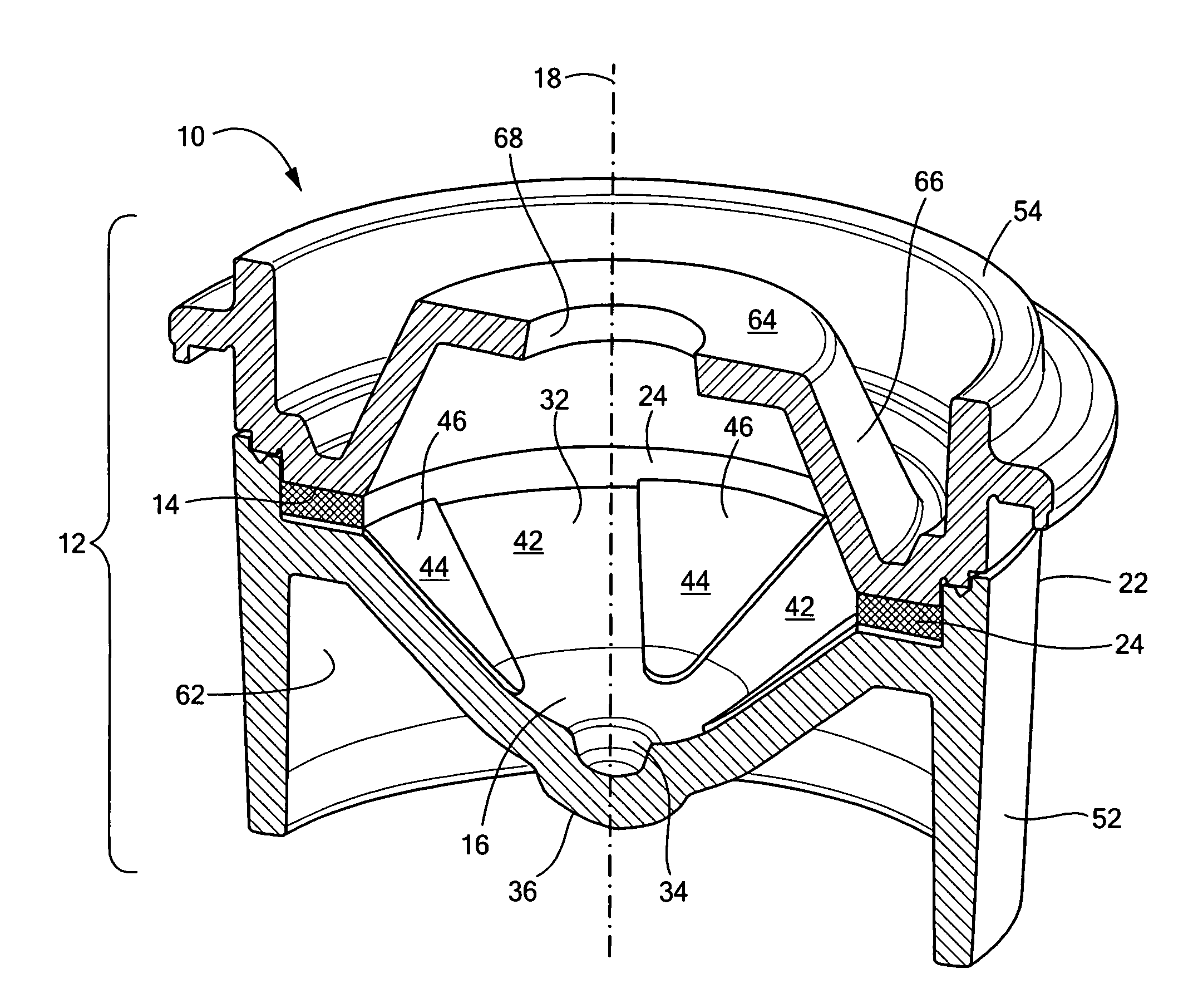
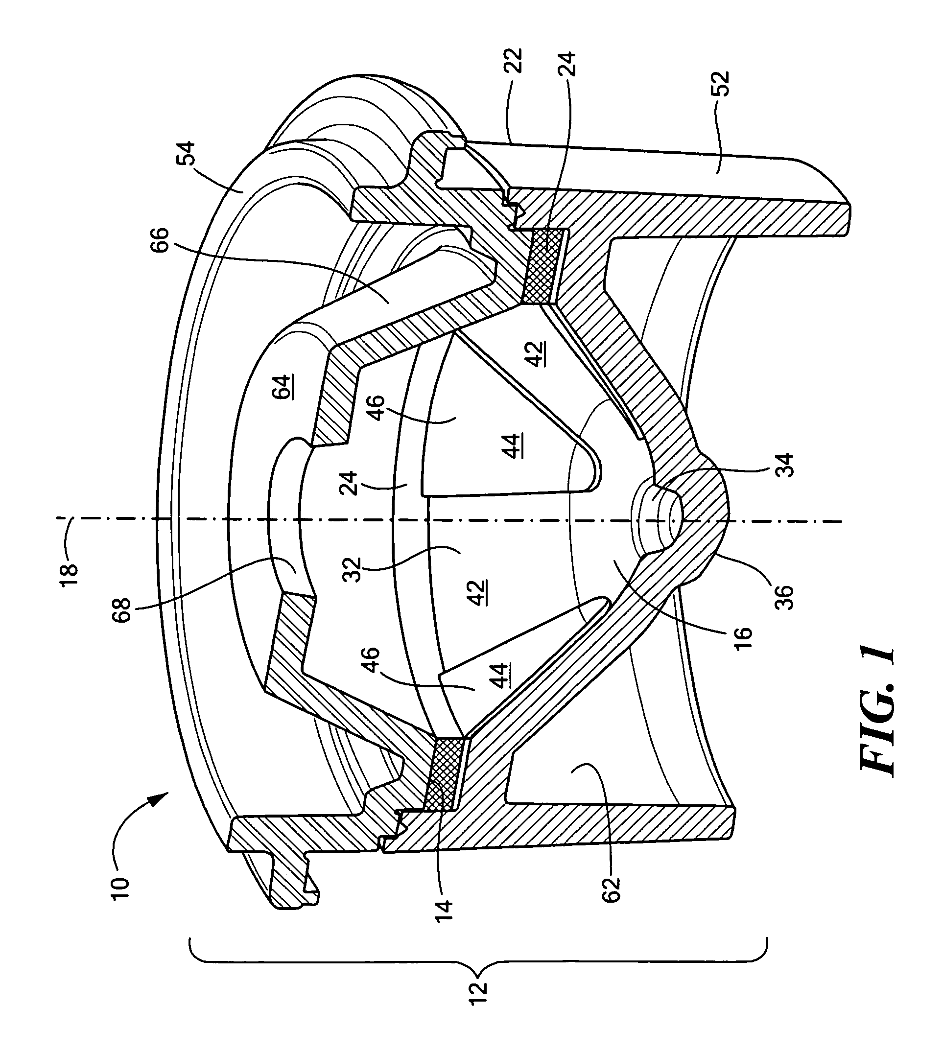
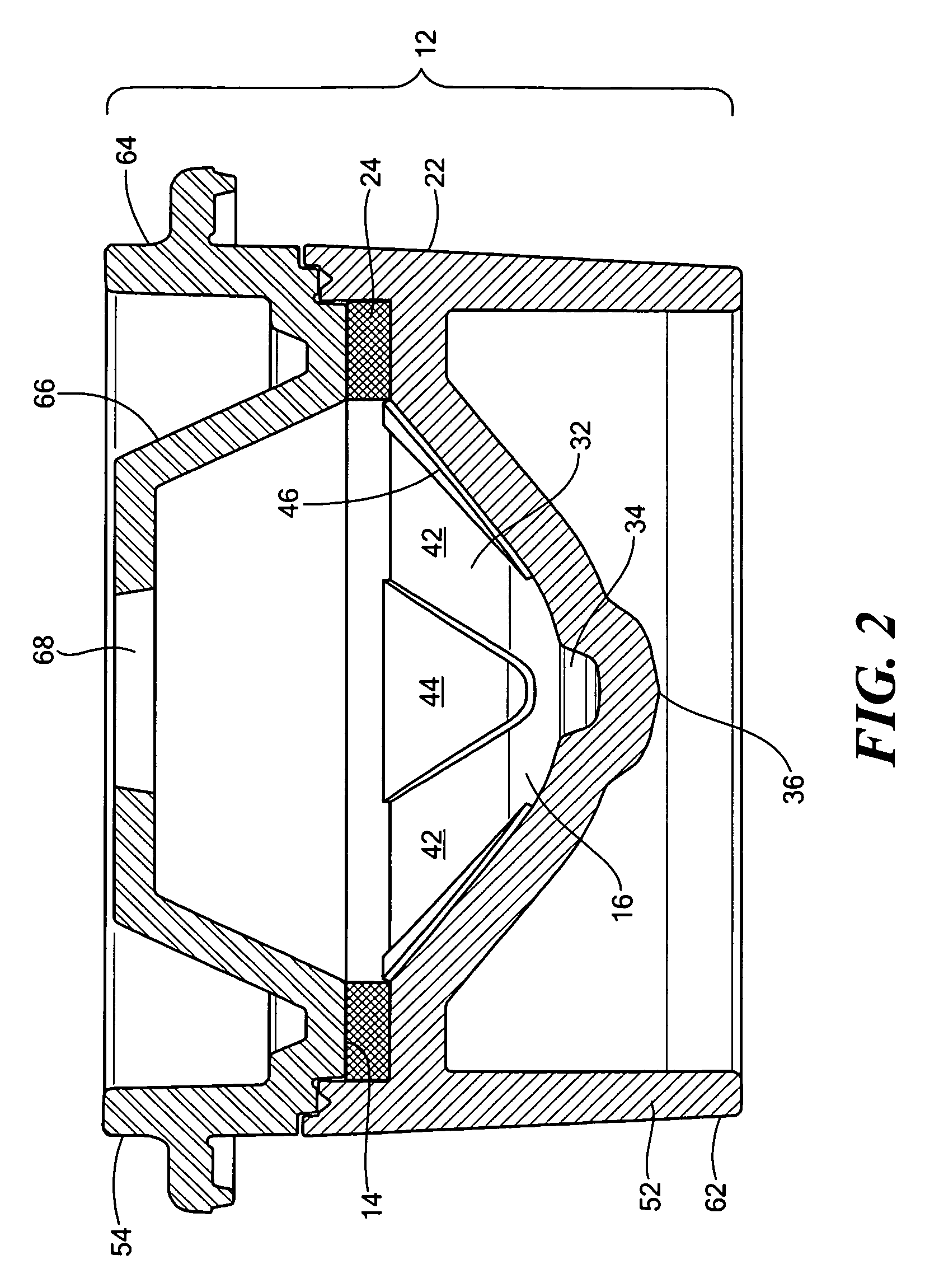
[0018]A centrifugal device 10 such as a cassette or rotor according to the present invention is illustrated in FIGS. 1 and 2. The rotor is particularly suitable for the separation of small sample volumes, such as less than 1 ml. The rotor includes a generally disc-shaped container housing 12 having a peripheral collection chamber 14 and a central collection chamber 16 arranged about a central spin axis 18.

[0019]The peripheral collection chamber 14 is preferably an annular chamber extending continuously about the peripheral circumference 22 of the housing 12. During manufacture, the peripheral collection chamber is filled with a controlled volume of a thixotropic separating gel 24, discussed further below. The gel is selected to have a density between the density of the various fluid components to be separated. Also, the gel is selected for its insolubility in the fluid components and for purity, inertness, viscosity, and time and temperature stability. Suitable gels for use in blood...


PUM

PropertyMeasurementUnit
volumesaaaaaaaaaa
timeaaaaaaaaaa
volumeaaaaaaaaaa

Abstract

A rotor is provided for the centrifugal separation of a composite fluid, such as animal or human blood, into components. An inner surface of the rotor includes at least one hydrophobic area having a first surface energy sufficiently low to provide a flow path for a lower density fluid component to flow to the bottom of a central collection chamber after centrifugal separation. A method of separating a composite fluid into components using such a rotor is also provided. Additionally, a method of manufacturing such a rotor is provided.

Description

CROSS REFERENCE TO RELATED APPLICATIONS[0001]N / ASTATEMENT REGARDING FEDERALLY SPONSORED RESEARCH OR DEVELOPMENT[0002]N / AFIELD OF THE INVENTION[0003]The present invention relates to the field of fluid centrifuging and in particular to the centrifuging of blood specimens.BACKGROUND OF THE INVENTION[0004]Human and animal blood specimens are frequently analyzed to determine the concentrations of components useful in diagnosis and preventive medicine. To perform these analyses, whole blood is separated into the components of plasma and particulates such as blood cells, or coagulated or clotted blood is separated into serum and the solids. Such separations are preformed by centrifuging. In centrifuging, the serum or plasma is lighter in weight and collects radially closer to the spin axis of the centrifuged container. A thixotropic gel, which has a density between the density of the blood cells and the density of the plasma, is generally used to maintain the separation between the blood c...

Claims


Application Information

Patent Timeline
Patent Type & Authority Patents(United States)
IPC IPC(8): B04B3/00B01D21/26B01D43/00
CPCB01D43/00B04B5/0407B01L3/50215B04B7/08B01L2300/0864B01L2300/0858
Inventor SOARES, TODD W.SULLIVAN, KEVIN
Owner IRIS INT
Why Eureka
Try Eureka