Method and generator for electrical discharge machining

a generator and electrical discharge technology, applied in the field of machine tools, can solve the problems of significant cost factor, unsatisfactory overall concept, expensive downtime, etc., and achieve the effects of reducing power loss, improving output frequency, and opening new technological horizons for users

Inactive Publication Date: 2011-05-24
AGIE CHARMILLES +1
View PDF21 Cites 5 Cited by
  • Summary
  • Abstract
  • Description
  • Claims
  • Application Information

AI Technical Summary

Problems solved by technology

To date there is still no satisfactory solution for a consistent overall concept.
These cables are a significant cost factor and if not designed with due care can easily result in expensive downtime.
This second cable has the disadvantage that the power losses, particularly in wire cutting, due to the high RMS value of the pulse current may be as high as 100 W / m.
Apart from this undesirable waste of energy this can also result in the machine structure becoming twisted from the heat and thus to work piece inaccuracies.
Currently, the only solution to this problem is a complicated means of water cooling.
Another disadvantage is also involved in the high rigidity of the cables used, typically needing to involve eight coaxial cables in parallel, each of approximately 5 mm2 copper section.
Since the cables are connected to moving structure parts of the machine, their rigidity results in flexing of these structure parts in the micrometer range and thus, of course, to corresponding errors in work piece machining.
This third cable likewise results in considerably costs because a great many different conductors are needed, but also because each machine variant needs ultimately a special cable.
A further disadvantage materializes when the machine 4 and the power cabinet 2 are shipped separately to the customer, the many connections of the cable system 3 required on installation constituting an added fault risk.
Although eliminating the load resistors improves efficiency, this is almost instantly reduced because of the commutations during the current peaks.
This disadvantage becomes all the more serious the higher the pulse current and the frequency are selected.
A further problem lies in a disadvantage of the bridge circuit itself, namely in the existence of switching elements between the work piece and the power supply, it being between these points that the steep commutation flanks result in high displacement currents at the AC mains side, ultimately resulting in poor electromagnetic compatibility.
For the same reason, the two sources need to be DC decoupled from each other which unnecessarily adds to the costs of the configuration.
However, both generators still have disadvantages.
Firstly, the pulse frequency is restricted to modest values of around 70 kHz due to monopolar charging.
Increasing the frequency further would allow the charge current to increase to values adversely affecting the efficiency.
Secondly, the generators are still too large to permit their location e.g. in the direct vicinity of the electrode.
Here, however, the switching elements of the full bridge need to commutate practically the total load current with high losses otherwise the ripple on the current would be 100% and a considerable amount of energy is inductively stored in the cable system.
All ignition sources of these generators comprise load resistors and are unable, for example, to regulate the pulse current or otherwise influence its shape.
Although generators of this kind were an advancement as long as the ignition voltage source was only used to generate a voltage (i.e. essentially without current) when attempting to also use the ignition voltage source for generating the smaller discharge currents (problematic for DC regulators because of the switching frequency being too high), however, the principle produced an unwanted drop in efficiency.

Method used


Image

  • Method and generator for electrical discharge machining
  • Method and generator for electrical discharge machining
  • Method and generator for electrical discharge machining

Examples


Embodiment Construction

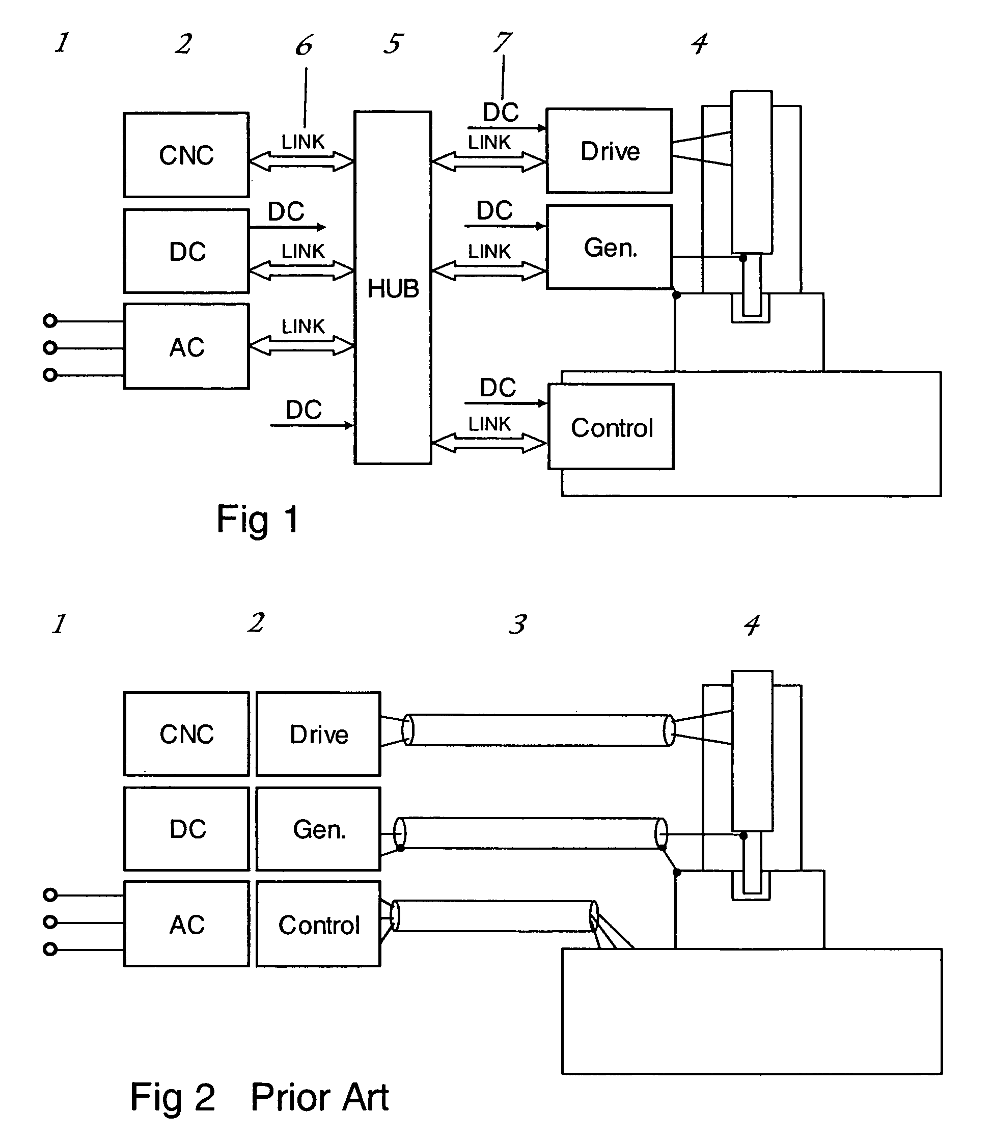
[0048]FIG. 1 illustrates the main modules of a die sinking machine which in this arrangement too, can be sub-divided into known modules, an AC mains input 1 with the subsequent AC module and a DC module. The power cabinet 2 is now considerably smaller, however, and can be housed in an operator console since the drive modules (Drive), the generator module (Gen.) and the universal machine control module (Control) are now all relocated in the machine 4.

[0049]The cable system 3 of FIG. 2 has been eliminated, it having been replaced by standardized data links 6 (LINK) which come together in a star configuration in a node 5. All information and commands from and to the various modules are also available for diagnostic purposes in the node 5. The node 5 is installed at a readily accessible location, but preferably on the machine 4.

[0050]The power supply of the various modules can be made directly via the data link 6 up to a wattage of approximately 50 W, standardized DC voltage cable 7 lik...


PUM

PropertyMeasurementUnit
frequencyaaaaaaaaaa
poweraaaaaaaaaa
DC voltageaaaaaaaaaa

Abstract

The invention relates to a method and a generator for generating a time sequence of discharge pulses separated from each other by pulse pauses for electrical discharge machining. At least two pulse capacitors are discharged each in the form of a partial pulse into the spark gap for forming together a discharge pulse. A discharge pulse having a predetermined waveform is selected from a plurality of discharge pulses having differing predetermined waveforms. The discharge of the at least two pulse capacitors is controlled such that the selected discharge pulse is generated with the predetermined waveform.

Description

FIELD OF THE INVENTION[0001]The invention relates generally to the field of machine tools, and more specifically the invention relates to a method of operating a machine tool and a machine tool, in particular to a method and a generator for electrical discharge machining (EDM), particularly for wire cutting and die sinking.BACKGROUND OF THE INVENTION[0002]Shown in FIG. 2 is the general configuration of a known type of EDM die sinking machine. A wire cutting machine differs from a die sinking machine actually only in details, but nevertheless most manufacturers make use of totally different concepts for the two types of machines. This applies particularly to the pulse generator involved, where very short but high discharge pulses are needed for wire cutting, whilst for die sinking longer discharge pulses of corresponding lower amplitude are used. To date there is still no satisfactory solution for a consistent overall concept.[0003]The configuration of an EDM system generally involve...

Claims


Application Information

Patent Timeline
Patent Type & Authority Patents(United States)
IPC IPC(8): B23H1/02
CPCB23H1/022B23H7/04B23H2300/20
Inventor BUHLER, ERNSTBESSON, FRANCKD'AMARIO, RINOGIANDOMENICO, NICOLAKNAAK, RETO
Owner AGIE CHARMILLES
Why Eureka
Try Eureka