Method for evacuating buildings divided into sections

Active Publication Date: 2011-05-24
SIEMENS SWITZERLAND
View PDF6 Cites 4 Cited by
  • Summary
  • Abstract
  • Description
  • Claims
  • Application Information

AI Technical Summary

Benefits of technology

[0008]The object of the present invention can be seen to be that of proposing a

Problems solved by technology

However, if necessary, a manua

Method used


Image

  • Method for evacuating buildings divided into sections
  • Method for evacuating buildings divided into sections
  • Method for evacuating buildings divided into sections

Examples


Embodiment Construction

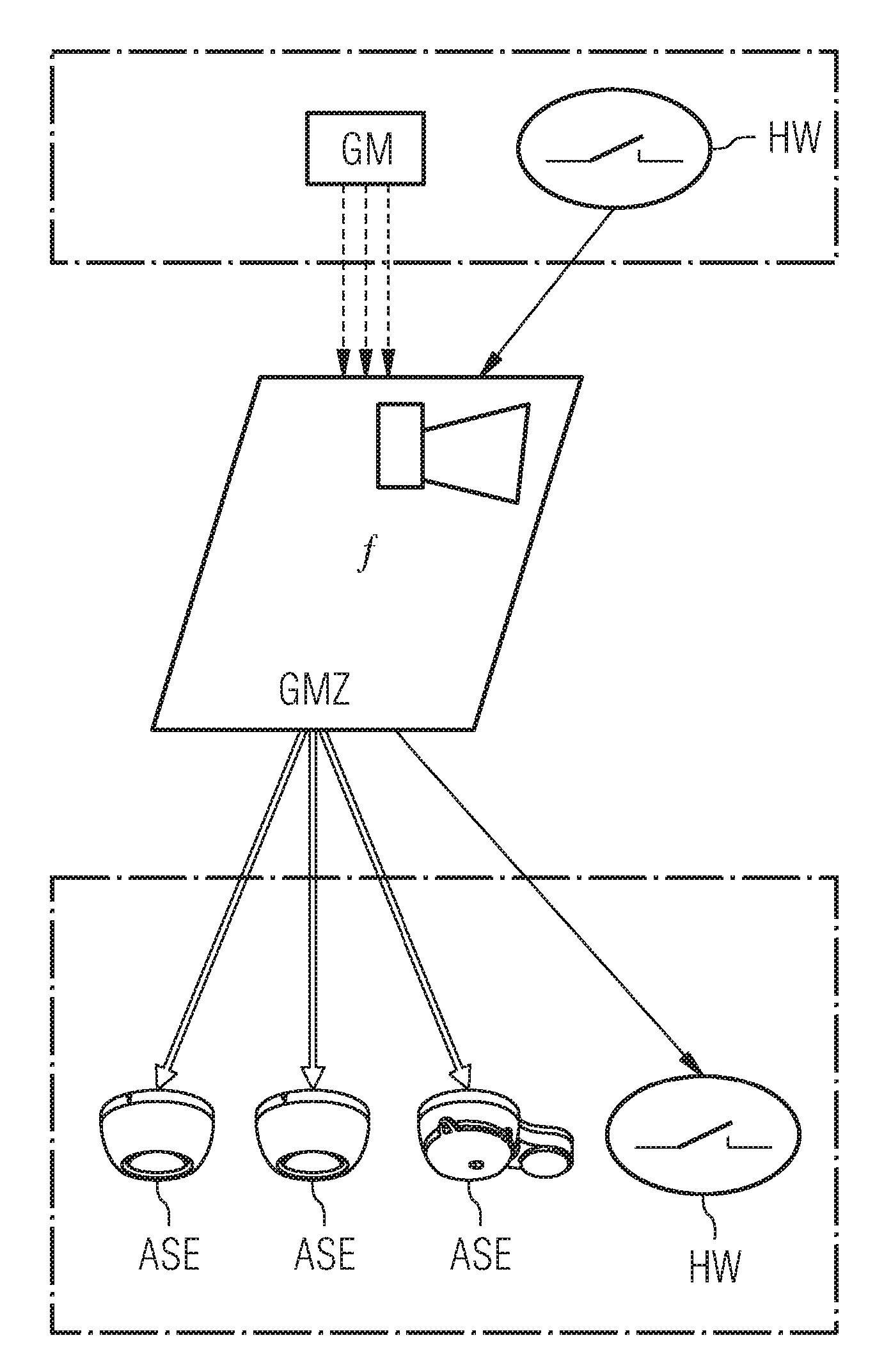
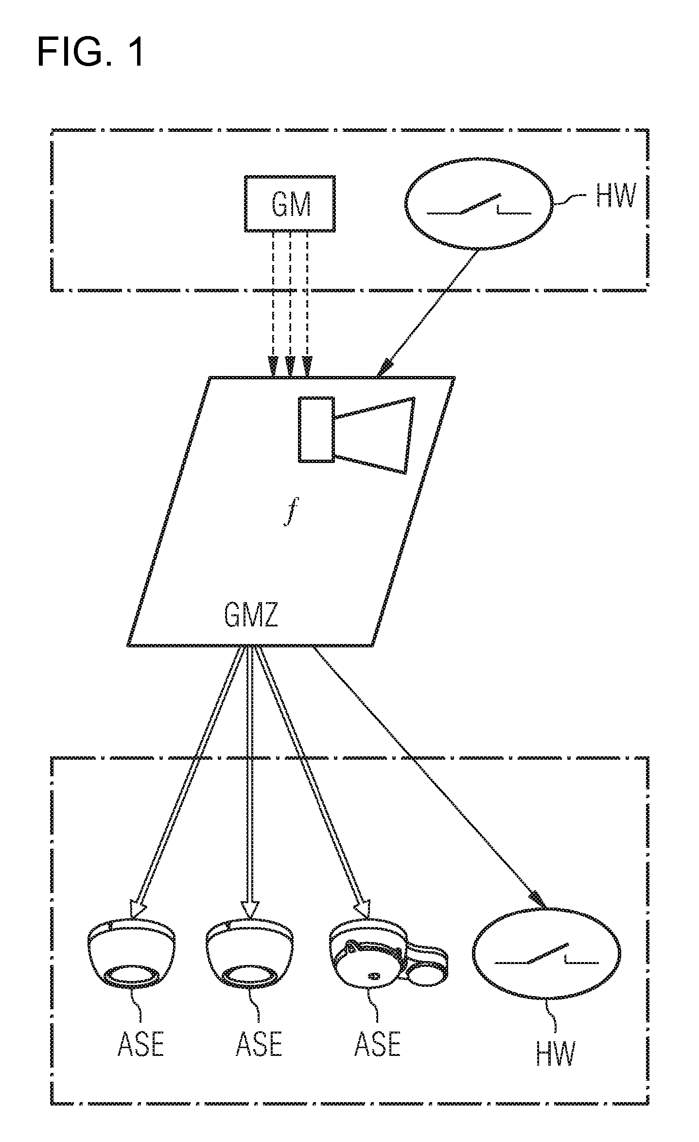
[0017]FIG. 1 shows a simplified illustration of an evacuation system according to the invention in a building. A hazard warning unit GM, for example in a room in a section, detects a hazard, for example a fire, and relays this hazard to the hazard warning center GMZ. Further units HW of the building can transmit parameters to the hazard warning center GMZ, for example by means of digital inputs of the hazard warning center, in order to evaluate the hazard. The evacuation plan can also be manually controlled or stopped using such digital inputs. The hazard warning center GMZ evaluates the data which are received from the hazard warning unit GM and relate to the hazard and creates an evacuation plan for the multistory building on the basis of the location of the hazard and at least one condition stored in the hazard warning center GMZ. This makes it possible to produce an evacuation plan which is individually adapted to the hazard, and it is thus possible to evacuate the people in the...


PUM


Abstract

A method, evacuation system and hazard warning center for the evacuation of a building divided into sections by the hazard warning center, which is connected to at least one hazard warning unit detecting a hazard. The hazard warning center produces an evacuation plan for the sections of the building on the basis of the location of the hazard detected by the hazard warning unit, the data received in connection with the hazard and at least one stored condition, and at least one alarm signaling unit in a section is sent at least one request to emit either a warning signal or an evacuation signal on the basis of the evacuation plan.

Description

BACKGROUND OF THE INVENTIONField of the Invention[0001]The invention relates to a method, to a hazard warning center and to an evacuation system for evacuating a building divided into sections by means of a hazard warning center which is connected to at least one hazard warning unit which detects a hazard.[0002]The term evacuation relates to the movement of people away from the location of a hazard, for example the clearing of an apartment, a house etc. The evacuation time is generally referred to as the evacuation duration.[0003]EP 401038 A1 describes an emergency evacuation arrangement containing a plurality of sensors for monitoring a hazard, such as smoke, fire or a tremor, in a respective area of a building. The arrangement has a processor which receives the signals generated by the sensors. The processor generates alarm warning signals and the signals which indicate escape routes. The driving of optical and acoustic indication means by the processor signals is used to indicate...

Claims


Application Information

Patent Timeline
IPC IPC(8): G08B29/00G08B5/00H05B39/00
CPCG08B7/066
Inventor HUBER, ANDREAS
Owner SIEMENS SWITZERLAND
Why Eureka
Try Eureka