
Error correction method and apparatus for predetermined error patterns

a predetermined error and pattern technology, applied in the field of error correction methods, can solve problems such as error pattern and start position of error pattern within the detected codeword, communication channel often tends to produce errors in specific patterns, and become corrupted

Inactive Publication Date: 2011-05-24
RGT UNIV OF MINNESOTA +1
View PDF15 Cites 39 Cited by
  • Summary
  • Abstract
  • Description
  • Claims
  • Application Information

AI Technical Summary

Benefits of technology

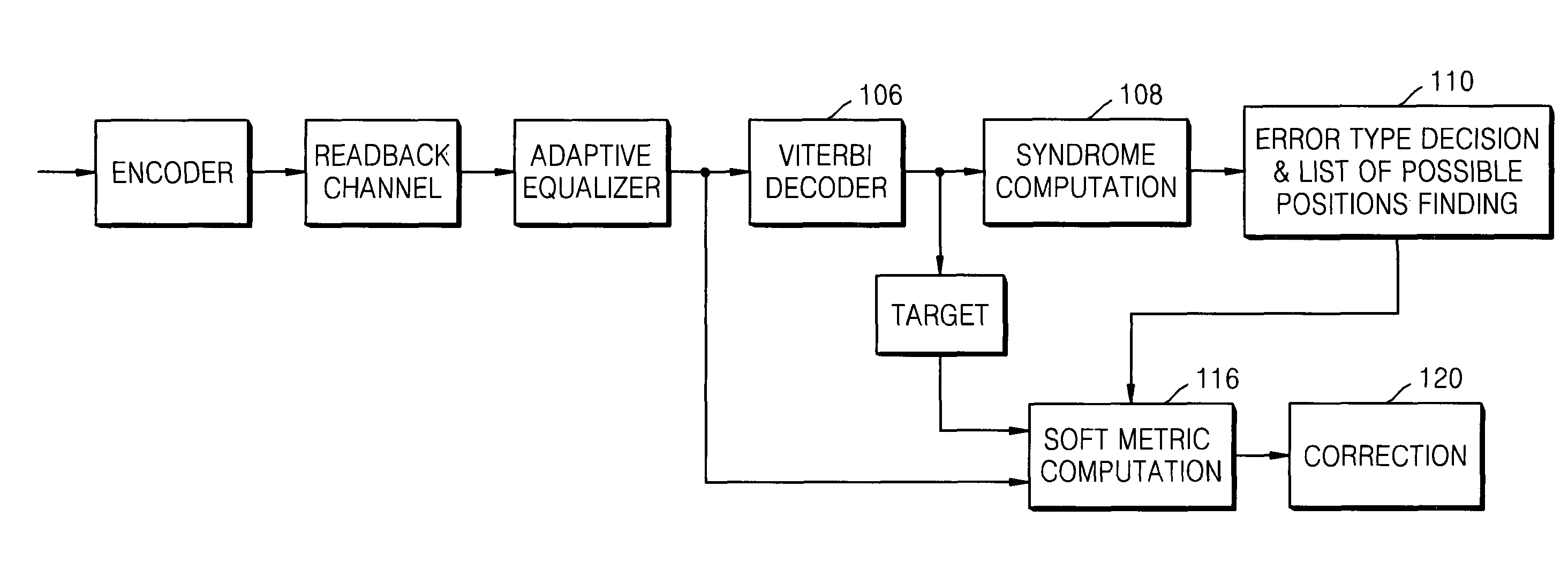
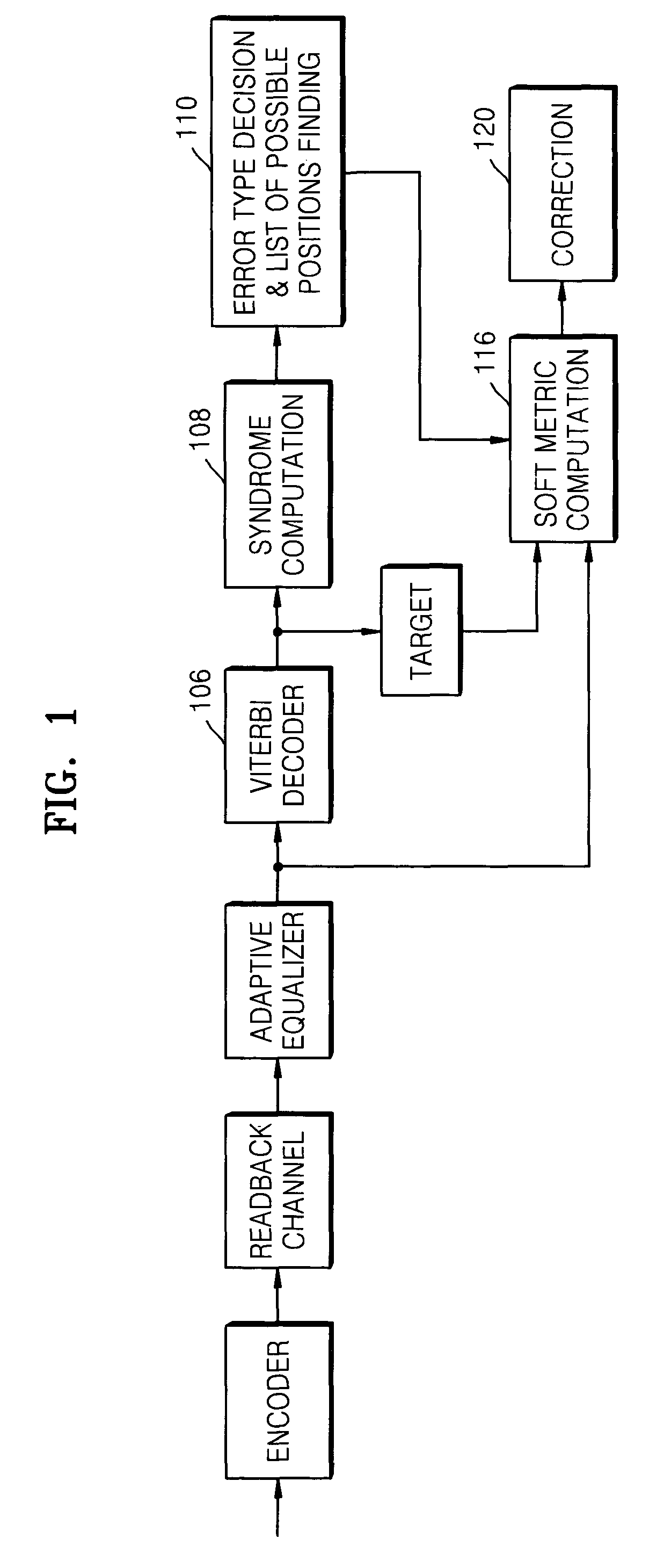
The patent describes a method and apparatus for detecting and correcting errors in a code transmitted across a noisy communication channel. The method involves detecting the code and generating a syndrome based on a generator polynomial that produces a distinct set of errors for each possible error pattern. The apparatus includes a decoder and a syndrome computation unit to detect and determine the type and start position of the error pattern. A soft metric computation unit calculates the potential start position of the error pattern and an error correction unit corrects the error pattern based on the type and start position. The technical effect of this invention is to improve the accuracy and reliability of data transmission across noisy communication channels.

Problems solved by technology

As the data is transmitted across the noisy channels, it may become corrupted.
However, the error detection and correction techniques allow the data to be restored to its original uncorrupted state.
A given communication channel often tends to produce errors in specific patterns.
When this technique is successful, it produces an error pattern and a start position of the error pattern within the detected codeword.
Unfortunately, the above technique has a tendency to mis-correct errors, either by predicting a wrong type of error pattern among the known error patterns, or by predicting a wrong position of an error pattern within the detected codeword.
Due to these mis-corrections, the above error-correction technique can have a negative impact on the performance of a communication system.

Method used


Image

  • Error correction method and apparatus for predetermined error patterns
  • Error correction method and apparatus for predetermined error patterns
  • Error correction method and apparatus for predetermined error patterns

Examples


Embodiment Construction

Exemplary embodiments of the invention are described below with reference to the corresponding drawings. These embodiments are presented as teaching examples. The actual scope of the invention is defined by the claims that follow.

Conventional block error correction codes (ECCs), such as BCH codes, are designed to have a minimum distance property that guarantees correction of up to “t” errors within a received data word. However, in interference-dominant channels, such as a readback channel in a high-density magnetic recording apparatus, errors tend to occur in specific patterns.

Although conventional error correction codes can correct some of these frequently observed error patterns, they are not very effective in correcting against all types of error patterns. For example, conventional techniques often fail to correct error patterns with a large number of non-zero bits, i.e., error patterns with high weights.

Embodiments of the invention provide a new approach to designing error corr...


PUM


Abstract

In a method of detecting an error pattern in a codeword transmitted across a noisy communication channel, a codeword is detected. A syndrome is then generated by applying a generator polynomial to the codeword. The generator polynomial is adapted to produce a distinct syndrome set for each of “L” (L>1) different error patterns potentially introduced in the codeword during transmission across the communication channel. A type of an error pattern within the codeword is detected based on the syndrome or a shifted version of the syndrome, and then a start position of the error pattern within the codeword.

Description

BACKGROUND OF THE INVENTION1. Field of the InventionEmbodiments of the invention relate generally to an error correction method. More particularly, embodiments of the invention relate to an error correction method capable of correcting single occurrences of predetermined error patterns.2. Description of Related ArtError detection and correction techniques play an important role in a variety of communication systems where data is transmitted across noisy communication channels. As the data is transmitted across the noisy channels, it may become corrupted. However, the error detection and correction techniques allow the data to be restored to its original uncorrupted state.Most error detection and correction techniques involve transmitting some form of redundant data across a communication channel together with a data payload. For example, redundant data such as a parity bit or a checksum may be combined with data to be transmitted, and then subsequently used to detect and correct err...

Claims


Application Information

Patent Timeline
Patent Type & Authority Patents(United States)
IPC IPC(8): H03M13/17H03M13/45
CPCH03M13/15H03M13/6331H03M13/17H03M13/09
Inventor PARK, JIHOONMOON, JAEKYUNLEE, JUN
Owner RGT UNIV OF MINNESOTA
Learn More